Maytag Rsc2O Page 134
Workshop Manuals
PICTORIAL
WIRING
DIAGRAM
Allow 10
percent
tolerance
on all
resistances
ICE
MAXER
RECEPTACLE
SCHEMATIC
WIRING
DIAGRAM
REFRIGI
SEE SERIAL
PLATE
FOR
SERIES
NUMBEI
LIGHT
swrTcH
I
->l
at
'l
I
I
I
I
/
COMPRESSOR
-^-
(\
| /Y-
lsucn0N
\
.,n.,
\k
t/'
K
v/
R,/
CAPACITOR
L-=
J"
DEFROST
TIMER
lr'
\1,
\
--t'
t;
L
':
CAUTION
This information is intended for
use by
quallfied
service
personnel
only.
Repalrs
performed
by
persons
unlamiliar
with this
product
could
result in reduced
performance
ol
a
safety
hazard.
8-9
CHANNEL
CABINET
LIGHTS
._ __
SWITCH
urOxi
TEMPERATURE
cor{PFilsER
+
I
8t"i?EF
/Wh
rEupERntuRe ,/ 5
co'waot
/ ^l
tl,'u',|r6'
t'J'ffJ'
wtRE coffi
co{oR cooE
REO
RD
WHITE WH
BLACX
BLX
ELUE BLU
YELLOW
8f,OWN BR
OfiAXGE OR
GREEI{ GR
GRAY GY
fi
lat rx
,,.de,RTD2l/
Contents Summary of Maytag Rsc2O
- Page 1r- 56326 ] andToPMount Side-By-Side Refrigerator ServiceManual svF-0289 PRINTED IN U.S.A. o Copyright1989 -- ,-a. l..r 4-- , ,.-.-.-,=--:..�
- Page 2INDEX SaBIECT PAGE SaBIECT PACE Meat Keeper 5-3 SECTION 1 . INTRODUCTION FreezerCold Control 5-4 MountingHardware 5-6 SECTION2 . INSTALLATION DrainTubes 5-6 StyrofoamDrip Tray 5-7 Specifications 2-1 CabinetDoors & Assoc.Parts 5'9 Warranty 2-4 PaintTouch-up 5-9 InstallationInstructions 2-5 Door Liner
- Page 3MI\YTAG SECTION I INTRODUCTION GENERAL T h i s m a n u a lco ve rsMa yta gR e fri ger atormanufacturs edbeginningin 1989.Thos em odel s c o v e r e da r e 1 5 , 1 7 , 1 9 , 2 0 , 2 1 , 2 2 , 2 3 a n d 2 4 c u b i cf o o t S i d e - B y - S i daen d T o p M o u n t r e fr i g e r a t ors. SAFETYPRECA
- Page 4M/\YTAG SECTION 2 INSTALLATION SPECIFICATIONS TOPMOUNT SIDE.BY.SIDE Models Models R T C1 5 A RTC19A RSC2OA RSD2OA R T S1 7 A RTD19A RSD22A R T C1 7 A RTD21A RSW22A R T D1 7 A RTW22A RSD24A R T S1 9 A RTD23A RSW24A 2-1�
- Page 5DIMENSIONS TOPMOUNT SIDE-BY.SIDE TI ffi E I A ry I t - B - - h r l r i o l eI :l rl ; l lrnl t r I r-----------------r-1 I " - i : *"1 ;i L - C Mod. No. A B c D E F G RTC15A 60" 29" 3 13 t 1 0 " 25 3t8" 27 5/8" 29 15t16" 55 3/8" R T S l7 A 641t2" 29' 313/10" 25 3t8" 275t8" 29 15/16" 55 3/8" RTCl7A 6
- Page 6CAPACITY Mod. No. TotalVolume Fresh Food Vol. FreezerVol. Total Shelf Area RTC15A 14.7 10.51 4.14 22.6 RTS17A 16.5 11.69 4.83 23.8 RTC17A 16.5 11.69 4.83 24.2 RTD17A 16.5 11.69 4.83 24.2 RTC19A 18.6 12.89 5.70 28.6 RTS19A 18.6 12.90 5.70 26.3 RTD19A 18.5 12.81 5.70 28.4 RTD21A 21.0 '14.59 32.5 6.42
- Page 7MAYTAG REFRIGERATOR WARRANTY Full One Year Warranty For one (1) year from the date of originalretail purchase,any part which fails in normalhome use will be repairedor replacedf ree of charge. Limited Warranty Secondthru Fifth Year - major refrigerationcomponents: Afterthe first year and throughthe
- Page 8INSTALLATION INSTRUCTIONS ELECTRICAL REQUIREMENTS OBSERVEALL NATIONAL ELECTRICALCODES AND LOCAL CODES & ORDINANCES ELECTRICAL SERVICE - 120VOLTS,60 Hz ONLY A 1 2 0v o l t ,6 0 H z, 1 5 a mp e refu se delectr icalsupplyis r equir ed.An individualbr a nc h( or s e p a r a t ec i rcu i tse rvi n go n l
- Page 9UNCRATING LOCATION 1 . L a ya p p l i a n c o en back. 1. Select a location for your new 2 . R e m o v eb otto mca p b y cu tti n g b and refrigerator away f rom any heat a n d p u l l i n gc a p a w a y . sour ces. Allow a fr ee flow o f ai r thr oughthe fr ontbasegr ille. 3 . R e m o v ec r a te b
- Page 10C o p p e rt u b i n g ( 1 1 4 "O . D . ) a n d s a d d l e This allows movement for the v a l v e c a n b e p u rch a se d f ro m local r efr iger atorwithoutdisconnec ti ng the h a r d w a r e sto re s. S w e a t o r f lar e tubing. Other r outing methods ar e c o n n e c t i o nca n b e u se d i
- Page 11I' P l u gi n t h e p o w e rco rda n d p u shthe r efr iger ator to the walt,ar r angingthe coppertu bi ng s o t h a t i t d o e sn o t vi b ra tea g a i n stthe backof the r efr iger ator or againstthe wall. IMPORTANT:Becausethe refrigeratorand ice maker are warm. tt may takeup to 12 hours before
- Page 12REVERSING DOORS Top MountModelsOnly Door reversal is NOT possible on those models that have a built-in ice and water lountain. However, if door removal becomes necessaryplease see the note in Step 9. Unplug Refrigerator. lf unit is in use, remove food from fresh food compartment 6 . Openr efr iger a
- Page 13Reversinglreezer door. H a n d l ea n d t r i m s h o u l db e c o m p l e t e l y r emovedfr omfr eezerdoor . 10.Take freezer door and remove screw 1 4 .Pr y plugson left side on top off w i th a from trim cap on the top of the door. flat bladescr ewdr ivertaking , car e not 1 1 .S l i d e b l a c
- Page 141 9 . W i t h g r i l l e n o w re mo ve d ,yo u have 22. Reinstallthe tr im cap and hingec ov er accessto the bottomhinge. Remove on the oppositesides. s c r e wf r o mth e si d eo f th e h i n g ecover . 23.Nowtake refrigeratordoor and remove scr ewfr om the tr im cap locatedon the bottomof the do
- Page 1529 .J u s t a s y o u d i d a b o vefo r th e tre e zerdoor ,moveall of the handleand tr im par tsto the o p p o s i t es id e o f th e d o o r a n d re i n stall.This is doneby r ever singthe stepsabove . N O T E : C are mu st o n ce a g a i n b e takento make sur e all spacerpads ar e r etur nedto
- Page 16DOORREMOVAL W ithassistance fr om someoneel s e to suppor t the tr eezer door , r em ov e bottomhinge by fir st r em ovin gs c r ew Side-By-Side ModelsOnly fr om side of hingecover and rem ov e cover . Unplug Refrigerator. lf unit is in use, 6. Pull wires and water line through remove food from the
- Page 17OPERATION Top MountModels SettingControls T h e s e m o d e l sh a ve tw o co n tro l s. One for r egulatingthe tem per atur ein the fr esh food compartmentand one for the freezer. The fresh food compartmentand the treezer c om p a r t m e nco t n tro l sa re l o ca te da t the top fr ontof the fr e
- Page 18USEOF CONTROLS fMPORTANT:Exceptwhen starting,do not changeeither controlmore than one number at a time. ALLOW24 HOURSFORTEMPERATURE TO STABILIZEBEFORE RESETNNG. C h a n g i n ge i th e rco n tro lw i l l h a vesomeeffecton the tem per atur of e the othercom par tm ent. T h e n u m b e r" 9 " l re e
- Page 19To st a r tt h e r e fri g e ra to r,se t th e re fri ger ator contr olon "D" and set the fr eezercontr ol " 6 " . L e t t h e r el fri g e ra torur n a t l e a st8 to 12 hour sbefor eloadingit with food. ln a d a y o r s o , i f th e co n su me rd e ci d e sthat one or bothcompar tments shouldbe co
- Page 20USEOF CONTROLS IMPORTANT:Exceptwhen starting,DO NOTchangeeither controlmore than one letteror one numberat a time. Allow 24 hourstor temperatureto stabilizebetore resetting. T o t u r n o f f t he re fri g e ra to r, se t th e r efr iger ator contr olon OFF. Warm CabinetSurfaces A t t i m e s ,t h e
- Page 21MITYTAG SECTION 3 SERVICE PROCEDURES GENERAL INFORMATION TOPMOUNTMODELS FORCEDAIR SYSTEMS O n a l l f o r c eda i r mo d e l s,a n a i r ci r culatingfan dr awscold air fr om ar oundthe evapor ator a n d d i r e c t si t to th e fre shfo o d a n d tr eezercompar tments. A car efullymeasur edam ounto
- Page 22EVAPORATION OF ICE CUBES (ropMount &side-By-side Moders) S in c ei c e c u b e sh a vea mo i stu reva p o rpr essur eabovethem,the vaporis constantlybei ng p ic k e du p i n t h e d ry a i r stre a ma n d depositedon the evapor atorThis . physicalchange k n o w na s " s u b l i m a t i o n i"s, t h
- Page 23SIDE-BY-SIDE MODELS S i d e - By - Si dmo e d e l sa re ma n u fa ctur ed with a singleevapor ator .They ar e autom ati c al l y d e f r o s t e db y a ra d i a n th e a te rw o rki ngin conjunction with an electr ictimer . T h e yh a v ea fa n co o l e dco n d e n sewith r the fan dissipating conde
- Page 24AIR FLOW Side-By-Side Models Th e e v a p o r a to ri s mo u n te d b e h i n d the The am ountof air being m oved in eac h cover at the rear of the freezer compart- dir ectionin the dr awing is br okendow n me n t . A c i r c u l a ti n gfa n i s mo u n te dnear as follows: t h e t o p o f t h e c
- Page 25CHECKING OPERATIOT\f - (A'Moders) T h e f o l l o w i n g g e n e ra l i n fo rma tionex- Exposethe dischar geend of the c api l l ar y p l a i n ss e v era lme th o dfo r ch e cki ngoper - and apply heat at this point. lf t her e i s a t i o n o f t h e re fri g e ra ti o nsyste m. This enough head
- Page 26SLOW LEAK IN SYSTEM DEFECTIVE COMPRESSOR O n f o r c e da i r m o d e l s ,l o n g r u n t i m e w i l l A compr essorwhich is not pum pingade- b e n o t i c e dd u ri n g th e e a rl y sta g e sof a quatelywill not cool effectively. All cool - lea k . As t h e r efri g e ra n co t n ti n u e sto es
- Page 27LEAK TESTING T h e f o l l o wi n g g e n e ra l i n fo rma tionex- T h e p r e s e n c eo f o i l a r o u n da t u b i n gj o i n t p l a i n s s e v e ra l me th o d so f ch e ckingthe usuallyindicatesa leak,but don' t l et thi s refrigeration syste mfo r l e a ks.T h i s infor - be the deter mini
- Page 28LEAKTESTING YODERLOOP Th e f o l l o w i n g g e n e ra l i n fo rma ti o nex- pla i n ss e v e r a lm e th o d su se d i n l e a k test- ing t h e y o d e rl oo p . Th e y o d e r l o o p i s ro u te di n th e fro n tcabi- n e t f l a n g ea t t he to p a n d si d e s.T h e yo der c on d e n s e lr
- Page 293 . U n s o l de r th e yo d e r l o o p tu bing at 9. Evacuateand r echar gethe sy s tem . p o i n t s" A " a n d " 8 " . 10.Leaktest all tubingjointsand tes t r un the r efr iger ator . 1 1 . P i n c ht h e p r o c e s st u b e a n d c u t t h e ser vicevalveoffthe tubing.Sol derthe joint and chec
- Page 308 . l n s t a l al n e wd r i e r . m oved withoutdistur bingthe r efr iger ant char ge. 9 . E v a c u a t ea n d re ch a rg eth e syste m. W hen using gauges to check operati ng 10.L e a kt e s t a l l tu b i n gj o i n tsa n d te st run pr essur es, obser vethesepr ecaution s . the refrigerator. 1
- Page 31d . H I G HS I D E- l o w e rp r e s s u r e dr ier ,evacuate,and r echar get he s y s - L O WS ID E- i n va cu u m tem. W AT T A GE - l o w e rth a n n o rm al f. H I G HS I D E- h i g h e rp r e s s u r e The system is probably restrictedat LOWSIDE- higherpr essu r e t h e e n t r a n ceo f th e c
- Page 32EVACUATING AND RECHARGING Th e f o l l o w i n gg e n e ra li n fo rma ti o n a p plies 500m icr ons,or 29.6inchesof vac uum t o a l l s y s t e m sco ve re d i n th i s ma n ual. o n a c o m p o u n dg a u g e .A f t e rp u l l i n ga vacuumfor 20 minutes,you can c l os e EVACUATING off the valveof
- Page 338 . Pu r g e th e te mp o ra ry re friger ant W ait at least 5 minutesafter the c har ge c h a r g eo u t t h e l o w s i d e .T h i sw i l l h e l p has enter edbefor estar tingthe c om pr es - t o r e m ovemo i stu refro m th e s ystem . sor. K e e p i n mi n d th a t th e p ro cess of f l u s h i
- Page 34SEALEDSYSTEMSWEEPCHARGE SERVICING PROCEDURES Sea l e ds y s t e msw e e pch a rg ep ro ce ssingis a modifiedpr ocedur ediffer entfr om the ev ac u- at io nm e t h o de mp l o yi n ga va cu u mp u mpand micr ongaugethatwer e usedin the past. T h r o u g he x t e n si vee va l u a ti o nw, e h a v eco
- Page 35N O T E:Al w a ysu se a p u rg eh o seo f sufficientlengthto dischar gethe r efr iger antout of the w o r k a r e a - p re fe ra b l yo u t d o o rs. Keep wor k ar ea well ventilatedwhen pur gin gor di s - c h a r g i n gr efri g e ra n t.WE A RGOGGLES TO PREVENT EYEINJURYwhen handlingrefr i ger - a
- Page 36PROCEDURE WITHCOMPRESSOR OPERATIVT 1 . F i l l c h a r g i n gcyl i n d e rw i th a t l e a st 6 ouncesmor e r efr iger antthan neededfor fi nal c h a r g eo f s yste m. P l u g i n ch a rg i n gcylinderheaterto r aise pr essur eto 30 lbs. abov e a m b i e n ct y l i n d e p r ressure. N O T E:M a i
- Page 375 . I n s t a l lh a n d va l ve a n d p u rg e h ose on a c c e s sva l ve . R o u tep u rg eh o seaway f r o m w o rk a re a- p re fe ra b l yo u tdoor s. 12. Attach hand valve to access valve. Char gein 4 oz. of r efr iger antfor l eak check. Close hand valve. W ai t ap- pr oxim ately5 m inutesfo
- Page 3819,I n s t a l lh a n dv a l veo n a cce ssva l vea nd char geof r efr iger ant.( Seepage3- 16, c h a r g et o f a c to rysp e ci fi e dch a rg e . Steps5 & 6.) 2 0 . C l o s eh a n d va l ve a n d q u i ckl yre move 5 . lnstall tempor ar y pier cing valve on i t f r o m a c ce ss va l ve . C l o se
- Page 39ative compr essorpr ocessstub. D o not installit on the replacementcom- pressorprocessstubor suctionline. Installa new r eplacement dr ier . 12. Connectchar ginghose to bo ttomof char gingcylinder . Attachhand v al v e to looseend of char ginghose , 13. Pur gechar ginghose with r efr i ger ant and c
- Page 4022. lnstallhandvalve on accessvalve and chargeto factoryspecifiedcharge. 2 3 . C l o s e h a n d va l ve a n d q u i ckl yre move it fr om accessvalve. Close lower valve on c h a r g i n gc y li n d e r,u si n gh a n d va l ve,slowly r eleaser efr iger antcontainedin char gi ng hose. 24. Put Teflon
- Page 41MAYTAG SECTION4 COMPONENTS COMPR.ESSON GENERALINFORMATION T h e f o l l o w i n gg e n e ra li n fo rma ti o ne xplainshow to successfully r eplacecompr ess or for s a n y m o d e lc ove re di n th i s ma n u a l . Al l r e p l a c e me nco t mp re sso rsa re char gedwith the cor r ectamountof oil a
- Page 42REPLACING THECOMPRESSOR 1 . D i s c o n n e ct ht e u n i tf r o mt h e p o w e rs o u r c e , 2 . L o c a t ed e fe cti veco mp re ssoar n d installa pier cingvalveon the pr ocesstube. 3 . I M P O R T AN C T ON N E C T A H OS ETO THE PIERCING VALVEAND DIRECTIT OUT OF D O O R S. O PE NT H EV A L V E
- Page 43d. M a k ea n o ffse t1 /2 i n chfro m the end of the cap tube to pr eventit fr om penetr ati ng t o o f a r i n toth e d ri e r. e . C u tt h e i n l e ttu b eo f th e re p l acem ent dr ier and use plier sto snapoff the scoredend. f. l n s t a l lth e n e w d ri e r u si n gsilversolderwith the pr
- Page 44HEAT EXCHANGER Th e f o l l o w i n gg e n e ra li n fo rma ti o e n xp lainshow to successfully r eplacethe heatexcha nger f o r a n y m o d e lco ve re di n th i s ma n u a l . REPLACING HEATEXCHANGER Top MountModels lf a l e a k i s f o u n d i n th e h e a t e xch a nger 11. Str aightenthe heat
- Page 451 7 . T r a n s f e rth e ru b b e rsl e e veto the r e- 23. Makean offset1/2"lrom the end of the p l a c e me n th e a t e xch a n g e ra nd tape capillar ytube and inser tinto t he new b o t he n ds. drier. 1 8 .I n s e r t h e h e a te xch a n g eirn tothe tube 24. Solderall connections. Applic a
- Page 467 . U n s o l d e trh e d ri e r fro m th e co n d e nser o u t l e t t u b e an d cl e a n th e o u tl e t.Re- mo v et h e d r ie r fro m th e ca p i l l a rytube s o t h e t u b i n ga sse mb l yca n b e p u l led t h r o u g ht h e t u b ee n t r yo p e n i n g . 8 . R e m o v et h e se a l e ra
- Page 471 9 .lnstallthe sponger oll on the new heat exchangerSeal . both ends wi th buty l sealer ,over wr apped with tape. 20. Car efullypush the heat ex c hanger s u c t i o n l i n e t h r o u g ht h e t u b e e n t r y holeat the r ear ol the tr eezerl i ner . 2 1 . Connect the electr ical components di
- Page 48CONDEJVSER e xp lainshow to successfully T h e f o l l o w i n g g e n e r a l i n fo rma ti o n r eplacethe condenserfor a n y m o d e l c o v e r e d i n t h i sm a n u a l . REPLACING CONDENSER Top MountModels IMPORTANT:THE FOLLOWINGPROCE- DUR E R E Q U I R E S T H E P L A C E ME N TOF BLOC K SO
- Page 4910.Removethe condenserscrews. 1 8 .S o l d e ra l l t h e j o i n t s .S i l v e rs o l d e ra n d pr operflux shouldbe used on c opper to steel or steel to steel join ts . F l ux should be wiped off the tubing after soldering. 19.Visuallycheckthe jointsfor leak s . 20.Connectthefan m otorwir e lead
- Page 503. Pl a c e a t hre e i n ch b l o ck u n d e r t h e dir ectingthe hoseoutdoor s.Leav ethe f r o n t o f t h e ca b i n e t.R e mo veth e two v a l v eo p e n . u n i tr a i l m o u n t i n g screws. 10. Clean the dischar ge tubing f or a distanceof about3 inchesat the poi nts you intendto cut or u
- Page 51FREEZER EVAPORATOR REPLACINGFREEZER EVAPORATOR plastic ties that secur e the w i r i ng har nessto the heatexchange r . Top MountModels 1 . D i s c o n ne ct th e u n i t fro m power 12. U n s o l d e rt h e s u c t i o nl i n e f r o m t h e source. com pr essor ,and the capillar y tube fr om the o
- Page 521 5 . T w i s t o n e b ra cke t to d i se n g age 22. lnstall the r adiant heater and e v a p o r a t o rdri p tra y fro m e va p o rator ter m inationther mostat. Then connec t tubing. the wir e leads. 1 6 . U n s o l d e rt h e ca p i l l a rytu b e a n d the 23,W or kingat the r earof the cabine
- Page 535 . Connecta hose to the service valve 1 4 . Rem ovethe tape and butyl ( r ubber ) a n d s l o w l y re l e a se th e p ressur e, sealer fr om both ends of the s ponge d i r e c t i n gth e h o seo u td o o rs. r oll that enclosedm uch of the heat exchangerThen . slide the sponger ol l 6 . U n s o l
- Page 5419. Po s i t i o n th e co i l a n d i n sta l l the 24. Evacuateand rechargethe system as m o u n t i n gs c re w s. instr ucted under "Evacuating and R e c h a r gnig" . 20. Transfer the radiant heaters to the r e p l a c e m e ncto i l . W h e n i n s t a l l i n gt h e 25. Test r un the unit to
- Page 55ELECTRICAL SYSTEM THERELATED COMPONENTS T h e w i r i n g di a g ra ml o ca te do n th e cabinetbackor behindthe gr ille depictsthe el ec tr i c al sy s t e mf o r th a t mo d e l .A l l e l e ctri calcom ponentsar e gr oundedto the cabinet.The gr een ce n t e rc o n d u cto irn th e p o w e rco rd
- Page 56lf ther e is evidence of ar cing, do not OVERLOAD PROTECTOR connecta jumper wir e, but pr oceedas follows: The overload protector prevents the c o m p r e s s ofrr om b u rn i n go u t i ts e l e ctr ical 1. Disconnect unitfr om powersour c e. win d i n g s i n t he e ve n t th e co mp ressor b e c
- Page 57and r un ter minalsof the com pr es s orT. hi s STARTINGRELAY device is connectedin par allelwi th the r un capacitor and in ser ies w i th the T h e s t a r ti n g re l a y e n e rg i zes the c o m p r e s s o rs t a r t w i n d i n g s . T h i s w i l l c o m p r e s s or sta rtw i n d i n g Wh .
- Page 585. Remove the PTC device from the com pr essor cir cuitto pr ovidethe r equi r ed c o m p r e s s o r. phase differencebetween the start and r u n w i n d i n g sf o r r u n n i n gt h e c o m p r e s s o r . 6 . U s i n g a n o h mme te r, ch e ck the resistance between the PTC device terminals. Th
- Page 59ALTERNATE METHODUSINGOHMMETER 1 . U n p l u gt h e l i n ec o r d . 2. Disconnectthe capacitorlead wires. 3 . S h o r ta c ro ssth e te rmi n a l su si nga r esistorwith a minimumr esistanceof 1000ohm sto b e s u r e n o ch a rg ere ma i n sto d am agethe ohm m eter . 4 . S e tt h e oh mme te se r l
- Page 60TEMPERATARE CONTROL Top MountModels Th e s e m o d e l sh a ve tw o te mp e ra tu rec ontr ols:fr esh food and tr eezercompar tmen t. T he f re s hf o o dt e m p e ra tu re co n tro lse n se sthe tem per atur e of its com par tment and gover n sthe c omp r e s s oor p e ra ti o na cco rd i n g l y.
- Page 61Al l o w t h e c o mp re ssoto r co mp l e tetwo or REPLACING THECONTROL t h r e e c o m pl e tecycl e s.l f th e te mper atur e r e a d i n g sa re n o t w i th i n tw o d e g r eesof r e q u i r e m en ts th e co n tro li s d e fe ctiveand 1. Disconnectthe unit fr om its pow er must be replaced.DO
- Page 62TEMPERATURE CONTROL Side-By-Side Models T h e t e m p e r a tu reco n tro l re g u l a te sthe CHECKOPERATING TEM PERATUR ES compressor running time while m a i n t a i n i n tgh e p ro p e rte mp e ra tu re ra nge A check of oper atingtemper atur eo f the REFRIGERATOR COLDCONTROL ca n be in t h e r
- Page 63T h e c u t - o u t te mp e ra tu re w i ll be check the contr ol oper ati ng a p p r o x i m a te lth y e sa me a s sp e ci fied.DO temper atur es. However , do not NOT ATTEMPTTO RECALIBRATE THIS overlook the possibilitiesof a C O N T R O LTh . e a d j u stme nscre t w sar e for malfunctioning f r
- Page 64ALTITUDE ADJUSTMENTS All Models :- The temperaturecontrolsusedon theseunitshavetwo adjustmentscrewsbothwhich must be turnedto compensatefor variancesin altitude, The chart showsthe exactscrew turns for each 1000feet of elevation. Notethe screw rotationsare designatedin graduationsof sixtieths.Theses
- Page 65DEFROST TIMER Top Mount Models The freezer evaporatordefrostingsystem is actuatedby an electrictimer.The timer is fastenedunderthe cabinet,behindthe grille. DEFROST THERMOSTAT TO COMPRESSOR FIBSTCLICK.DEFROST OPERATION 1st Click - The tim er switches off the compr essorand tr eezer fan circ ui t for
- Page 66CHECKING DEFROST TIMER Disc o n n e cat l l w i re s fro m th e ti me r and a t t a c ho h m m e te rp ro b e sto th e te rmi nals s p e c i f i e di n t h e a cco mp a n yi nch g a rt.l f no continuity is indicatedthe timer is defective. TO TEST TURNTIMER CHECK KNOBTO BETWEEN TERMINALS TimerMotorCi
- Page 672nd Click - The timer switches off the CHECK1NG DEFROST TIMER defrostcircuit and startsthe compressor, f r e e z e rf a n , a n d th e co n d e n sefa r n motor . The compressorand fan motors are now Disconnectall wir es fr om the timer and governedby the temperaturecontrolfor a attachohmm eterpr ob
- Page 68DEFROST HEATER AND THERMOSTAT Top MountModels Th e s e m o d e l s u se a ra d i a n t h e a ter to heater even when the evapor ator rem o v e a c c u mu l a te d f ro st f ro m the t e m p e r a t u ries * 1 5 oF o r h i g h e r . lree z e r e v a p ora to r a n d d ra i n tro ugh d u r i n ga d e
- Page 69To test the defrostheaterand thermostat 4 . Slide the fr eezer bottom out of the w h e nt h e e va p o ra tote r mp e ra tu rei s * 15o cabinet. F o r b e l o wp ro ce e da s fo l l o w s: 5 . Remove the evapor atorcove r . l t i s 1 . D i s c o n n e ct th e u n i tf ro m p o w e rsour ce ver y im
- Page 703 . R e m o v et h e d e fro stth e rmo staat n d mountingclip. This is done by squeezing"in " on c l i p a n d p u l l i n gu p t o d i s e n g a g e . 4 . I n s t a l tl h e d e fro stth e rmo staitn th e r ever seor derof r em oval. NOT E : W h e n re i n sta l l i n gma , ke su re you snap ther
- Page 714. The meter should read between 42K 4 . Disconnect unitfr om wattmet er . a n d 6 3 K o h ms.T h e re si sta n ceis not c r i t i c a l.A s l o n g a s th e re i s co ntinuity 5 . FollowSteps2, 3 and 4 of tes ti ngthe b e t w e enT e rmi n a l sN o . 2 a n d 3 the heater and ther mostat when the de
- Page 724 . R e m o v e t he a u g e r a n d so me shelf b y m e r e l ys p r i n g i n ge i t h e rs i d eo f t h e c l i p r e t a i n e rc l ip s. out. 5 . Removethe lower freezer evaporator cover. Disconnect the defrost heater e l e c t r i c a l l e a d s f ro m th e ca binet wiring. 7 . R e m o v et h
- Page 73CONDENSERFAN All Models T h e c o n d e nsefa r n i s co n n e cte di n par allel operate it is defectiveand rnust be w i t h t h e c omp re sso r.l f th e co mpr essor r eplaced. r u n s b u t t h e fa n d o e sn 't,th e fa n i s either d e f e c t i v e o r d i sco n n e cte d .l f neither operate
- Page 74FREEZER FAN Top MountModels The lreezer fan circulates cooled air read about40 ohms. lf the freezertan throughout the fresh food and freezer is inoper ativethe meter should r ead c omp a r t m e n t .Th e fa n b l a d e i s ma d e of appr oximately 150ohms. poly e t h y l e naen d i s p u sh e do n
- Page 75REPLACINGTHE FREEZERFAN 1 . F o l l o wSte p s1 th ro u g h7 o f checking t h e f r e eze rfa n . 2 . R e m o veth e fa n b l a d eb y p u l l i ngit off the shaft. 3 . R e m o v eth e scre w s th a t se cur e the m o t o rt o th e mo u n ti n gb ra cke t. 4 . I n s t a l l th e mo to r i n th e mou
- Page 761 . D i s c o n n e cth t e u n i t fro m th e p o wer operate, the motor or its leads is source. Remove the freezer fan defective. d i s p e r s i n sgh i e l d . 5. The r eplacement m otor will be 2. Removethe upper evaporatorcover. attachedto the bracket in the same Y o u w i l l h a veto d ri ve
- Page 77MI\YTAG SECTION5 CABINET AND @RELATED COMPONENTS FOOD LINER Al l f o o d l i ne rsa re ma d eo f a stu rdyplasticmater ialwhichhas a glossysur faces i m i l ari n a p p e a r a n ceto p o rce l a i nl i n e rs.A ll m odelsar e pr oducedwith foam ed- in- place in s ul ati on and their finerscannotbe
- Page 78Side-By-Side Models CANTILEVER SHELFTRIM To remove: The cantilevershelftr im is easilyr em ov ed by placingthe shelfon a flat wor k sur fac e and using a str aight scr ewdr iver to 1 . L l f tt h e r i g h te n d u p s l i g h t l ya n d p u s h car efullypr y on the r ollededge.The tr i m t h e s h
- Page 794. Lift the fr ont of the dr aweran d pul l i t REFRIGERATED MEAT out of the shelffr am e. KEEPER 5. The dr aweris installedin the r ev er s e or derof r emoval. The meat keeper has a shuttercontrolto a d j u s tt h e a mo u n to f a i r a d mi tte di nto the NOTE: The meat keeper drawer can be pan
- Page 80air flow to the treezercompartmentwhich, ther efor e,fur therlower sthe tem per atur e of the freezercompartment. By tur ningthe fr eezercold contr olknob towar da lower number ,you incr easethe air flow of chilledair into the fr esh food com par tment.This will incr easethe fl ow of chilled air to
- Page 816 . Pull the lreezerchestbottomout of the 12. Place the styrofoamassembly on a c a b i n e t. work surface and remove the orifice a n d d a m p e ra s s e m b l yb y p u l l i n gu p t o 7 . Remove the styrofoam lreezer coil fr ee dam pershaftfr om cr ank. c o v e r .l t i s ve ry i mp o rta nto t r
- Page 82FREEZER COLDCONTROL TWISTNUTS Side-By-Side Models This type of nut is usedto m ountpar ts i n the refrigeratorand treezercompartment. T h e f r e e z e rc o n tro li s a me ch a n i cabl affle They ar e installedbefor ethe cabinet i s t h a t c a n b e ad j u ste d to re g u l a te the foam insulate
- Page 83SERVICE ON DRAINTUBE STYROFOAMDRIPTRAY All Models l f t h e d r a i ntu b e i s cl o g g e dca , re fu llypush a r o u n d o b je cta b o u t 1 1 4 "O.D .d o wn the Top MountModelsOnly p i p e .T h e n fl u sh i t w i th w a rm w a ter until t h e f o o d p a rti cl e s,ca u si n gth e p roblem, are
- Page 841 0 .Separatethe styrofoamdrip tray from the fresh food compartmenttop by removingthe d a m p e ra n d o ri fi cea sse mb l y.T h i s is done by pullingdamperand or ificeassemblyup to free dampershaftfrom crank. 1 1 Position . the replacementdrip tray on the freshfood compartmenttop. 12.Transferthe
- Page 85CABINET DOOR^SAND ASSOCIATED PARTS 5. Closeand openthe doorsever alti m es PAINTTOUCH.UP and checkthe gasketfor pr opers eal . Paintedareas of the cabinetor doors that 6. Car efullyopen the door by pu l l i ngon become scratched or marred can be the m iddlesectionof the door panel . t o u c h e d u
- Page 86DOORLINER 4. Removethe upperhingeand placeon top of unit with newspaperor cl oth under neath to pr eventscr atchingThe . Side-By-Side Models door will r em ainheld in place by the magneticaasket.Do not m isplacethe Th e i n n e r d o o r l i n e r a n d th e d o o r g a s ket plasticspacer s. a re m
- Page 87REVERSING DOORS DOORCLOSER T o p M o u n tmo d e l s,w i th th e e xceptionof Side-By-Side Models m o d e l s h a vi n g i ce o r w a te r th ro ughthe d o o r , a r e ma n u fa ctu re dw i th re v er sible o p e n i n gd oo rs. T h e i n stru cti o n sfor this Ther e ar e no specific door c l os er
- Page 88REMOVABLE SHELF GUARDS WHEEL e-[fi'?" CLIP A ll d o o r s h e l fgu a rd sa re e a si l yre mo v ed. Th e m o d e ly o u se rvi cema y h a ve a w ide and a l s o a n a rro w g u a rd . E a ch typ e is mo u n t e db a s i c a l l yth e sa mee xce p tfo r the WHEEL WITH n u m b e ro f c l i p s . LOCK
- Page 89To lock the cabinetin place,lock wheels. IMPROVING GASKET SEAL TOE.IN& TOE.OUTADJUSTMENTS In or der for the gasket to seal ev enl y ar ound the entir e door , it mus t m ak e contactat the top and bottomat the same time. For this r easonthe door ,when aj ar , shouldnot toe- inor toe- out. To cor r e
- Page 90c. The distancebetweenthe door and The door panelis par allelwith the cabinetis greaterat the top than it cabinettop. is at the bottom,or vice versa. In many cases, leveling the refrigerator d . T h e h a nd l esi d e o f th e d o o r d oes will eliminatethe need for cabinetdoor n o t l i n e u p w
- Page 91WATER COMPONENTS WATERSUPPLY C e r t a i n mo d e l s a re e q u i p p e d with "t h r o u g h t h e d o o r" ch i l l e d w ater /ice dispensersand/or automaticice maker. M o d e l sw h ich h a veth e seo p ti o n srequir e t h e i n s t a l l ati o on f a co l dw a te rsu p plyline. For installati
- Page 92REPLACING TUBINGFROM THE WATER 3. Rem ove the water valve mounti ng VALVETO THE ICE MAKER scr ew and disconnect the compressionnut from the water valve supplyingthe chilledwaterfounta i n. 1 . S h u t o f f t h e e l e ctri ca lsu p p l y to the unit. 4. Removethe cr ispershelf. 2. R e m o v e t he
- Page 93RESERVOIR TO PLASTICUNION 7. Installthe par ts in the r evers eor der of r em oval and avoid any c r i m ps , 1 . D i s c o n n e ct th e u n i t fro m power bends or kinks that m ight c aus e a source. r estr ictionin the tubing. 2. Remove those parts necessary to L Tur n on the electr ical suppl y
- Page 947 . Install the r eplacem entr eser voi r i n WATERRESERVOIR the r ever seor derof r emoval.You m ay needto lubr icatelineswith a silic one gr ease. REPLACING THEWATER Reconnectthe unit to Power sour c e RESERVOIR and activate the chilled wa ter dispenserDr . awsix or sevenglas s es of water to remo
- Page 953 . Removethe crispershelf. 9. Reconnectthe unit to power s our c e 4 . From the back, disconnect the and activate the chilled water reservoirinletand outletcompression dispenserDr . awsix or sevengl as s es nuts and drain the water into a of water to remove any trapped air. container. Checkeachconn
- Page 96FOANTAIN ASSEMBLY ICECHUTE SEAL.ICE CHUTE CHECK-VALVE COVERCOMPRESSION UNION COMPBESSION UTS COMPRESSION UNION W I R EC L I P FOIL W I R EH A R N E S S HEATERCONNECTOR ADJUSTABLESTRAP G R O U N DW I R E U - N U T- G R O U N D I N G HEATERWIRES HEATERFOUNTAIN(Sx s only) CONDUIT SWITCHBRACKET S W I T
- Page 974 . Pull the escutcheontowardsthe door h a n d l e to sn a p , o r d i se n g agefr om fasteners. O n S i d e -B y-S i d e mo d e l s, pull escutcheonawayfrom door handle. 5 . Removewire cover by removingtwo screws. You now have accessto the selector, lightand lockswitches. NOTE: To check trap door
- Page 982 . Remove the dash-pot piston from m ountingbr acketby r emovingtr u- ar c r ingand spr ingwasher . 3 . Removepistonarm by pryingclip off. 4 . Replacethe dash-potin the reverse order of removal. REPLACINGTHE SWITCH ASSEMBLY 3. Remove two (2) screws to remove The switch assemblyincludes ice a nd swi
- Page 99WATERAND ICE FOUNTAINHEATER ACTIVATINGSWITCHES NOTE: The fountain heater is only on (GH|LD-PROOF SAFETYSWTTCH) Slde-By-Side models. The fountainheater is a nesistancetype heater used to evaporateany moisture that mightaccum ulate fr om condens ati on. The fountain heater is bond ed to a self- adhesi
- Page 100CHECKINGFOUNTAINHEATERWIRE l f a f a u l t y h e a t e r w i r e i s s u s p e c t e di t c a n e a s i l y b e c h e c k e dt h r o u g h t h e c o n n e c t i o n a t t h e b o t t o md o o r h i n g eb e h i n dt h e g r i l l e . 1. Disconnect the unit from power source. 2 . R e m o v et h e g r
- Page 101Removethe wire connectionsand attach AUGERMOTOR the meter probes to the switch t e r m i n a t i on s.D e p re ssth e sw i tchplunger . T h e m e t e r w i l l sh o w co n ti n u i tyif it is operative.lf the switch proves operative a n d t h e p r o b l e m i s sti l l p re se n t,check treezerdoor
- Page 102MI\YTAG SECTION 6 ICE MAKER INSTALLATION Top MountModels PREPARING THEFREEZER Remove the existing air duc t by r em ovingmountingscr ewand s l i di ng it to the left out of the channel . T hi s 1, Unplug the refrigerator power cord par t is no longerr equir edwhen us i ng from the wall outlet. the i
- Page 1032. After selection,slide the air du c t, bottomcor nerfir st,intothe slot on the leftside of the r ear air tunnel. Fasten the air duct to the r ear fr eezerwal l with one Type"A" scr ew. FILLTUBE 3 . Plugthe ice m akerpowerplugintothe _--17@ A--- FILLTuBEGRoMMET ice m akerelectr icalr eceptaclein th
- Page 1045 . Reassemblethe plastic treezer ctivider 2. Locate water valve power plug and a n d s h e l v e s . R e p l a c et h e 2 s c r e w s i n water line inside machine t h e f r e e z e rd i v i d e r . M a k e s u r e f r e e z e r compartment. Remove both the d i v i d e r i s l e v e l a n d t i g h
- Page 1058 . Sl i d e n u t a nd sl e e ve o n to th e w a ter Sweat or flare connectioncan be used s u p p l yl i n e ( S te p3 .) In se rtth e e n d of instead of the compr essionunion, i f th e t u b i n gi n toth e co mp re ssi o u n n i on desir ed. a s f a r a s i t w i l l g o . S cre w in c o m p r e
- Page 106I t 5 . Locatethe brassnut and sleevewhich 7 . Connect the waterlinefr omthe s addl e ,, c o m e w i th th e sa d d l e va l ve . Slide valve to the water valve as shown in t h e m on to th e 1 1 4 " co p p e r tubing. Step4 and 5. Inser tthe waterli ne i nto I n s e r tth e e n d o f th e tu b i n
- Page 107Side-By-SideModels PREPARINGFREEZER INSTALLING ICE MAKER 1. Plugthe ice makerpowerplugintothe 1 . UNPLUG THE REFRIGERATOR ice makerelectr icalr eceptaclein the POWERCORDfrom the wall outlet. left side of the cabinet. Obser vethe patternof the metal pins. They must 2 . Movethe refrigeratorout from th
- Page 108INSTALLING WATERVALVE 3 . Locate water valve power plug and AND CONNECTING TUBING water line inside machine compartment.Removeprotectivecap Workingfrom the rear: fr om water line and discar d. Sl i p the plasticnuton waterline. 1. For the 22 and 24 cubic foot models, removethe centerscrewfrom the ri
- Page 109ir-'--t -l ] *ATERVALVE PowER PLUG WATERVALVE 1. Find a 318"to 1" ver ticalCOLDwa ter J--.-_pl"l I pipe near the r efr iger ator . W a ter w^m;-rslruu.Ji^l'fi il*'\ pr essur em ustbe between20 and 120 MTG. HOLES P.S.l. Ver ticalpipe is pr efer able, b ut a hor izontalpipe will wor k. lf a hor izonta
- Page 1109. Plug in the power cord and push the COLDWATER LINE r e f r i g e r a t o rt o t h e w a l l , a r r a n g i n g t h e copper tubing so that it does not CLAMPS vibrate against the back of the r e f r i g e r a t o ro r a g a i n s tt h e w a l l . BRASSSLEEVE BRASSNUT COPPER TUBING IMPORTANT: Beca
- Page 111.'ERVICING The design of this ice maker allows all of the components to be tested without TESTPROCEDURES removing the ice maker or moving the refrigerator away from the wall to access the water valve. lce Maker Pluggedln To Power Shut-OffArm Down-Freezer Cold Remove the cover and you will see the t
- Page 112( M a k e su re th a t th e tr eezer M O D U L E ,M O T O RA N D S U P P O R T t e m p era tu rei s co l d e n o u g hto close ASSEMBLY- t h e b i m e ta l .) Insert phillipsdriver in access ports in m o d u l e . L o o s e nb o t h s c r e w s . D i s c o n n e c t NOTE:Do not shortany contactsothe
- Page 113CAUTION NEVERROTATE THE BLADE OR THE DRIVE GEAR...ITWILL RUIN THE MAIN ASSEM BLY. Ther ear e sever alswitcheswhichwill j am if manuallytur nedcounter clockwi sand e the gear s will be destr oyedif tur ned clockwise.)lf you needto advancethe i c e maker into the cycle, use a jum pe r to br idge H to
- Page 114WHATHAPPENSDURINGBLADEROTATION WaterValve Energized 7.5Secs 140Fiil Ejector Blade Stop position (about 1:30o'clock) / EjectorStallsOn lce (1/2MinuteTo 5 Minutes) Thermostal OpensIn This RangeOf Rotalion 6 o'clock ViewedFromFront Position (ModuleSide) NOTE: Do nottestif bladesarepastrestposition. O n
- Page 115NOTE:Someice makerswill havea water NOTE: Onlythe ther m ostat, mold,wi th adjustmentknob. Pull off the knob to heater & wir ing har ness ar e removecover. Be sure to replaceknob in r eplaceable. Any other fail ur e s am es e t t i n gp osi ti o n . ( including the motor ) r equ i r es r eplacemento
- Page 116U s i n gn e e d l en o se p l i e rs,g ra spone of the ther mostatclips and pull out. Pr es si n new t h e r m o s t a t,ma ki n gsu re th a t p i n s ar e pr oper lyindexed. Usingthis pr ocedur e,i t i s not n e c e s s a r toy re mo veth e e l e ctri calassembly.lf you ar e r eplacingthe m odule,
- Page 117LEVELING OF ICEMAKER Assureuniformice crescents Loosen Level l/M by sliding lell or right in slot ol bracket Tighten Ma k es u r e r e f ri g e ra toirs l e ve lfro n tto back( Adjustlegsor r oller s.) REMOVING & REPLACING FILLCUP T o r e m o v ef i l l cu p yo u mu stse p a ra temoldand blade f r o
- Page 118WIRINGHARNESS T h i s h a r n e ssp l u g sd i re ctl yi n tol i n er r eceptacle. OTHERINFORMATION Motorconnectorscan be damagedif leadsare removed. T h e m o t o ri s a va i l a b l eo n l ya s p a rtof the completemoduleassembly. On e ( 1 )r e v ol u ti o no f b l a d eta ke s3 m inutes( * stallt
- Page 119MAYTAG SECTION 7 TROUBLE SHOOTING TOP MOANT AND SIDE.BY.SIDE MODEI'S 7'-1�
- Page 120TROUBLE P OS SIBLE CAUSE REMEDY A . U n i td o e s n o t r u n . N o N o power at AC distributionpa- 1. Check and advise customerto light in refrigeralor. nel of house. callan electrician. A C outlet. 2. a . Defectiveoutlet. a. Advise customer to have defectiveoutletreplaced. b. Open circuitto AC ou
- Page 121TROUBLE P OSSIBLE CAUSE REMEDY E . U n i tr u n sc o n t i n u o u s l y 1. Substantialloss of sealed sys- 1. Locate and repair leak before but there is no cooling tem charge (low wattage read- rechargi ng. in refrigerator and in g s ) . freezer compad- 2. Restrictedcapillaryor drier on 2. Replacede
- Page 122T R O U BL E P O S S I B L EC A U S E REMEDY Unit runs excessively Freezerfan. o r c o n t i n u o u s l yT. h e a. Defectivefan motor. Replace. refrigerator and b. AC circuit to fan open Refer to wiring diagrams freezercompartments (lowerwattagereadings). a n d c h e c kc i r c u i t . are cooling
- Page 123TROUBLE P O S S I B L EC A U S E REM EDY Unit runs excessively. '1. Padial restriction in air duct 1. Check and remove what is Refrigeratorcompart- from freezer to refrigerator. causingthe restriction.See "Air ment eventuallygets F l o wD i a g r a m " . cold enough but freezer compartment 2. Freeze
- Page 124T R O U BL E P OS SIBLE CAUSE REMEDY M . U n i t r u n s a n d c y c l e 1. Defectiveor misadjustedtem- 1. Adjustcontrolor replaceif nec- about normally. Both peraturecontrol. essary. compadmenls cool- i n g ,b u t n o t e n o u g h . N. Unit runs and cycles. Poorfreezerdoor seal. 1. Adjustdoor or r
- Page 125T R OU B L E P OSSIBLE CAUSE REMEDY R . Excessivelynoisy but 1 . Refrigeratornot level or firmly 1. Level the unit, lower the level- works normally other- settingon all four corners. ing legs if necessaryto make wise. sure thal unit is firmly on the floor. 2. Structuralweaknessin floor. 2. Advisecus
- Page 126M/\YTAG SECTION8 SCHEMATICS INDEX t- 8-1�
- Page 127PICTORIAL WIRINGDIAGRAM SCHEMATIC WIRINGDIAGRAM Allow 10 percenttoleranceon all resistances JRet conot RADIANT HEATER DIVIDERHEATERSWITCH t----:- DIVIO€RCHANNEL HEATERWIRE r------------'l Rp< .-LD-.] tCf, ilAXER l_!! __ _+>_w_[ L-_i:gt'r__io.'#@*s I lflrlixrrcrn iGR WATERVALV WIRE CODE D I V I ORE C
- Page 128PICTORIAL WIRINGDIAGRAM SCHEMATIC WIRINGDIAGRAM Allow 10 percenttoleranceon all resistances I C EM A K E R FAN,MoroR * grYrqEsJ*EAr! B SWrLc! RECEPTACLE STti DEFROST DIVID€RCHANNEL THERMOST HEATERWIRE r---- - - - - - - - -'1 | | wH .-wH '-i--i:gY--fo.'#@*** .Lo_.j tcf, maKER IEn WATERVALVE w r R Ec
- Page 129PICTORIAL WIRINGDIAGRAM SCHEMATIC WIRINGDIAGRAM Allow 10 percenttoleranceon all resistances r l rJRet __.tcoao I RADIANT r---: - - - :-- - -;:-- ICEMAKER HEATER DIVIOERHEATERSIVITCH- - - RECEPTACLE FAN MOTOR : REFR OIVIDERCHANNEL HEATERWIRE r------------'l I l-![------r .l_D_.I 'iEffi&Hr tc€ TAKER |
- Page 130PICTORIAL WIRINGDIAGRAM SCHEMATIC WIRINGDIAGRAM Allow 10 percenttoleranceon all resistances ICEMAKER DIVIDERHEATER SIYITCH RECEPTACLE r-**:- ;Li-- r I llEofi L|e}{T | | ,:;*qmffi^ WIRE CODE DIVIDER COLOR co0E REO RD WHITF WH BL ACX BLX ELUE BLU .flB,#F' ,\i?fJ, !#iF$ YELLOW BROWI{ ORANG€ 8R OR WATER
- Page 131PICTORTAL WIRINGDIAGRAM SCHEMATIC WIRINGDIAGRAM Allow 10 percenttoleranceon all resistances J'Rrt CORD+ ICEMAKER 1 HEATER r 2 6 A r _,qryr gEsJE arg8.swrlcH RECEPTACLE CHANNEL HEATERUIIRE r---- - - - - - - - -'l I a r w i w HH - - -. . w H '-i--rW--io:g@u* ,LD_.l tCEXAf(ER ' -le.V/ -'. L__**______[
- Page 132PICTORIAL WIRINGDIAGRAM SCHEMATIC WIRINGDIAGRAM Allow 10 percenttoleranceon all resistances I I RADIANT I C EM A K E R HEATER OIVIOERHEATER SWITCH RECEPTACLE I ?!Ar REFRI L- - - - - -l- - - jEgl-tr$L - -l - -,i . uRr{Ess I' ExtiD DIVIDER CHANNEL LINER HEATER WIRE r ) ' ' ( t - - - - t l l w f l t l
- Page 133PICTORIAL WIRINGDIAGRAM SCHEMATIC WIRINGDIAGRAM Allow 10 percenttoleranceon all resistances l- ?J,Re t I RADIANT ICE MAKER RECEPTACLE FAN MOTOR. ffi:"i1-t REFRIGE DIVIO€R CHANNEL HEATER WIRE ----- ( t-------'aTTE:1! ' | ,, l-![---- .Lo_.; - rct rgt6ngEol |irr{ ^' II i--iP--f':J6*u ! lsfrtt iGR ..rN/
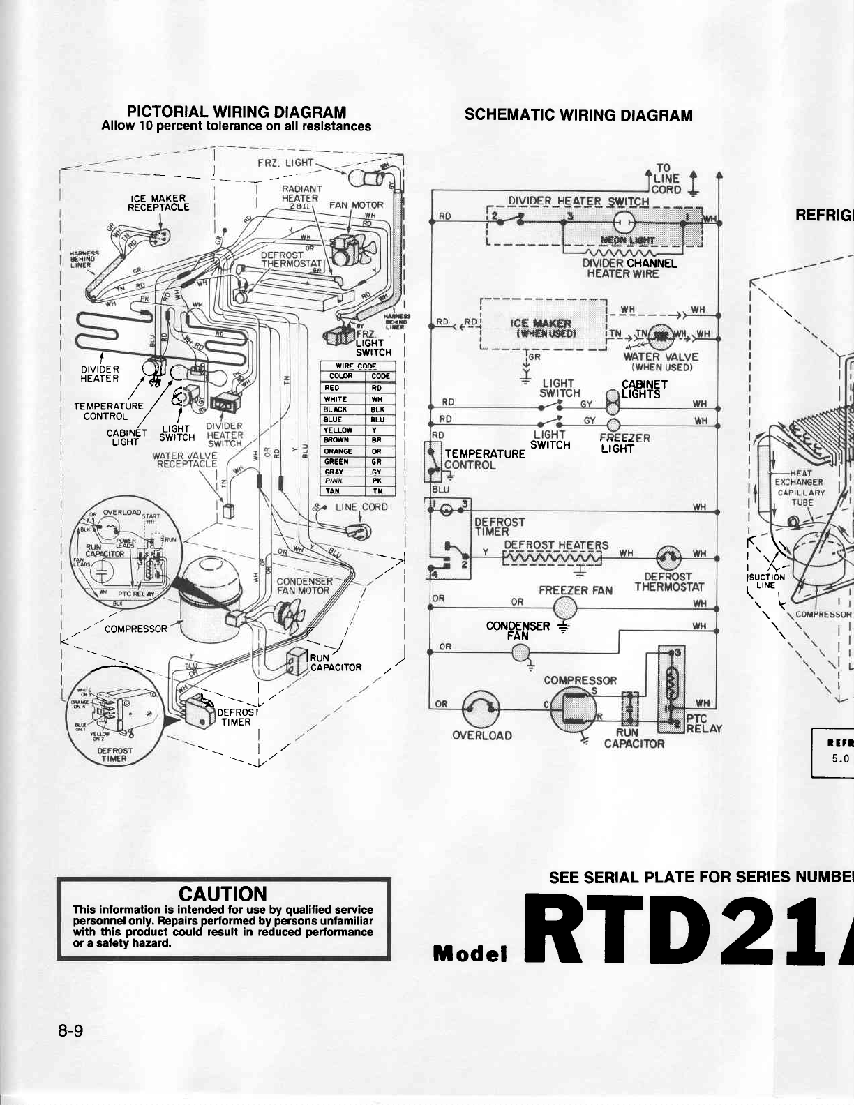
- Page 134PICTORIAL WIRINGDIAGRAM SCHEMATIC WIRINGDIAGRAM Allow 10 percenttoleranceon all resistances ICE MAXER RECEPTACLE REFRIG CHANNEL LIGHT swrTcH I 8t"i?EF wtRE coffi co{oR cooE rEupERntuRe /Wh ,/ 5 REO WHITE BLACX RD WH BLX CABINET LIGHTS co'waot ELUE BLU / ^l tl,'u',|r6't'J'ffJ' YELLOW 8f,OWN BR OfiAXG
- Page 135PICTORIAL WIRINGDIAGRAM SCHEMATIC WIRINGDIAGRAM REFRIG Allow 10 percenttoleranceon all resistances I rr -\ I ICE MAKER MOTOR I R E c E p r a c L /E. _ t I FAN MOTOR r r z r nI D I V I DR E HEATER TEMPERATURE CONTROL Foun'rNtflBu'$Ftr,o[r*^X^ r"i,?iJ, ,-"J"yi- \.o-z\LrGH/ sATiix SELECTOR D"'JI?EE SWt
- Page 136PICTORIAL WIRINGDIAGRAM SCHEMATIC WIRINGDIAGRAM Allow10 percenttoleranceon all resistances I RADIANT ICEMAKER RECEPTACLE | -54.ttEI FANMoroR L------L-*!q$$m- | OVIO€RCHANNEL HEATER WIRE t WIRE CODE D I V I D ER H E A T ER COLOR co0E RLO RO /*/ WHITE WH reueeRarune / 8L ACX gLX coNTROl- ALUE EIU i/ r
- Page 137PICTORIAL WIRINGDIAGRAM SCHEMATIC WIRINGDIAGRAM Allow 10 percenttoleranceon all resistinces .- =:-.-T |.:- r------------1 iI rcr uaxen | | -w H ..WH RECEPTACLE. l r - - I EL.L0-.1 tcE tAxER i ,--r I L- iigT]--io:g@.ur I l|lerqrrcDltl iTN -TNt-\Wl.l -W I I i FREEZER Ien WATERVALVE I LIGHT on YI (WHEN
- Page 138PICTORIAL WIRINGDIAGRAM SCHEMATIC WIRINGDIAGRAM REF Allow 10 percenttoleranceon all resistances TO -----^, r-- -- | WH ,L INE CORD t | - - -. . W H t{ iil€ss r .i--iW'__io,,g@',u+ .Lo_.l tcf f,at(ER , EHtfro LITER\ IAA WATERVALVE WAI LIT YFLV FREEZER YI (WHEN usEo) LIGHT . swrTcH> = ":"Y LIGHT UPPER
- Page 139PICTORIAL WIRINGDIAGRAM SCHEMATIC WIRINGDIAGRAM Allow t0 percenttoleranceon all resistances =-.7 I i I C EM A K E R r-- -- ! RECEPTACLE I r wH ..wH HANrlESS EH|l{0 .-i--:H'__fo:;$vr* e{_Dj rcf, ilAxEF I LINER FREEZER iGR WATERVALVE L|GHT - (WHEN I w r r s r t vUSED} eEv, swrTcH2 Y ,*y F -t=!-olt uPP
- Page 140-.. PtgToRtAL WtRtNG Allow 10 percenttoleranceon att ieslsiinces DTAGRAM SCHEMATIC WIRINGDIAGRAM REFRI REFR|G L .| G H I _ sry_-- FREEZER ^:._ 1^ \FRzr-rGHr i=.ice r,raxen R E CE P T A C L E CHILDPROOF SELECTOR WATERO I S P SWITCH VE (LO\fER) REFRIG. AQ.T..-uAJoR f e,_* A;- wH LIGHT I H NE$ EHIiO ;A
- Page 141PICTORIAL WIRINGDIAGRAM SCHEMATIC WIRINGDIAGRAM Allow 10 percenttoleranceon all resistances | " CONTROL 'ilxHilTdr .E_D_.I tcE UAKER HAFiEss , NR€SS I I EH|l{O L I N E R- trxtio Ltlfl - -- *jfi - - - - -'J _ fo3$@.+xo I I FREEZER ff ilil,.S,-y3r.y,. LIGHT . I wnEt! ui Y I swrrcn) RO lx * utcxt uppER
- Page 142PICTORIAL WIRINGDIAGRAM SCHEMATIC WIRINGDIAGRAM REFRIG Allow 10 percenttoleranceon all resistances 6p652gp REFRTG. F3!-- .- - - ={tr u,qn MAKER ]JTA I UNTAINHEATER LrcHrs'tvrrcH _FppM3lN CHILOPROOF swrTcH (LosER) R€FRIG. LIGHT I WIRE 2940Jr! FOUNTAIII.I LIGHT 'swtTcH LIGHT UPPER swtTcfl SWITCH (I]IR
- Page 143SECTION 9 f-. i --. -' SPECIFICATIONS INDEX 9-1�
- Page 144RTCl5A TEMPERATURE CONTROL 11sVAC (At Normal) POWER REOUIREMENT don. C u t - O u l( P l u so r M i n u s 1 . 5 ' F ) + 23"F C u t - l n( P l u s o r M i n u s 1 . 5 o F ) + 330F FAN oPERATTNG AMPS.(MAX) 6.6 CONDENSER COOLED CAPILLARY TUBE REFRTGERANT CHARGE R-12(02) 5.0 Length 5.5ft. Diameter 026"t.
- Page 145RTS17A TEMPERATURE CONTROL 11sVAC (At Normal) POWER REOUIREMENT 60 Hz C u t - O u t( P l u so r M i n u s 1 . 5 " F ) + 230F C u t - l n( P l u s o r M i n u s 1 . S o F ) + 330F FAN oPERATTNG AMPS.(MAX) o.o CONDENSER COOLED CAPILLARY TUBE REFRTGERANT CHARGE R-12(02) 5.U Length 5.5ft. Diameter . 0 2
- Page 146RTCl7A TEMPERATURE CONTROL 11sVAC (At Normal) POWER REOUIREMENT 60 Hz Cut-Out(Plusor Minus1.soF) + 230F Cut-ln(Plusor Minus1.5oF) + 330F FAN oPERATTNG AMPS.(MAX) b.b GONDENSER COOLED CAPILLARY TUBE REFRTGERANT CHARGE R-12(02) q n Length 5.5fr. Diameter .026"t.o. DEFROST THERMOSTAT G0MPRESS0R 0rL CHA
- Page 147RTDl7A TEMPERATURE CONTROL 11sVAC (At Normal) POWER REOUIREMENT 60 Hz Cut-O0t(Plusor Minus1.5oF) + 230F C u t - l n( P l u so r M i n u s1 . 5 o F ) + 33.F FAN oPERATTNG AMPS.(MAX) o.o CONDENSER COOLED CAPILLARY TUBE REFRTGERANT CHARGE R-12(02) c.u Length 5.5fr. Diameter 026"t.D. DEFROST THERMOSTAT
- Page 148RTSl9A TEMPERATURE CONTROL 11sVAC (At Normal) POWER REOUIREMENT 60 Hz C u t - O u t( P l u so r M i n u s 1 . S o F ) + 230F C u t - l n( P l u s o r M i n u s l . S o F ) + 33.F FAN 0PERATTNG AMPS.(MAX) o.o CONDENSER COOLED CAPILLARY TUBE REFRTGERANT CHARGE R-12(02) 5.0 Length 8 ft. Diameter .036"t
- Page 149RTC19A TEMPERATURE CONTROL 1IqVAC (At Normal) POWER REOUIREMENT 60 Hz C u t Q u t( P l u so r M i n u s1 . 5 ' F ) + 23"F C u t - l n( P l u so r M i n u s1 . S o F ) + 33oF FAN oPERATTNG AMPS.(MAX) 6.6 CONDENSER COOLED CAPILLARY TUBE REFRTGERANT GHARGE R-12(02) c.u Length 8ft. Diameter .036"r.D. DE
- Page 150RTDl9A TEMPERATURE CONTROL 11sVAC (At Normal) POWER REOUIREMENT 60 Hz CulOut (Plusor Minus1.SoF) +230F Cut-ln(Plusor Minus1.SoF) + 330F FAN 0PERATIl'lG AMPS. (MAx) 6.6 CONDENSER COOLED CAPILLARY TUBE REFRTGERANT CHARGE R-12(02) c.u Length 8fl. Diameter , 0 3 6 "t . D . DEFROST THERMOSTAT C0MPRESS0R
- Page 151RTD21A TEMPERATURE CONTROL 11sVAC (At Normal) POWER REOUIREMENT 60 Hz C u f O u t ( P l u so r M i n u s 1 . 5 o F ) +23"F Ctit-ln(Plus or Minus 1.50F) + 330F FAN oPERATTNG AMPS.(MAX) 6.6 CONDENSER COOLED CAPILLARY TUEE REFRTGERANT CHARGE R-12(02) 5.0 Length I ft. Diameter . 0 3 6 "t . D . DEFROST T
- Page 152RTW22A TEMPERATURE CONTROL 11sVAC (At Normal) POWER REOUIREMENT 60 Hz C u t - O u(tP l u so r M i n u s1 . S o F ) + 230F C u t - l n( P l u so r M i n u s1 . S o F ) + 33.F FAN 0PERATTNG AMPS.(MAX) 7.2 CONDENSER COOLED CAPILLARY TUBE REFRTGERANT CHARGE R-12(02) 5.0 Lenglh 8 tt. Diameler .036"t.D. D
- Page 153RTD23A iJ TEMPERATURE CONTROL 11sVAC (At Normal) POWER REOUIREMENT 60 Hz C u f O u t ( P l u so r M i n u s 1 . 5 " F ) + 23.F C u t - l n{ P l u so r M i n u s 1 . S " F i + 33"F FAN 0PERATTNG AMPS.(MAX) 6.6 CONDENSEB COOLED CAPILLARY TUBE REFRTGERANT CHARGE R-l 2(02) 5.0 Length I ft. Diameter 036"
- Page 154RSC2OA TEMPERATURE CONTROL 11sVAC (At Normal) POWER REOUIREMENT 60 Hz Cut-Out(Plusor Minus1.5"F) +22"F C u t - l n( P l u so r M i n u s1 . 5 o F ) + 340F FAN oPERATTNG AMPS.(MAX) 6.5 CONDENSER COOLED CAPILLARY TUBE REFRTGERANT CHARGE R-12(02) o.c Length 8ft. Diameter . 0 3 1 r" . D . DEFROST THERMO
- Page 155RSD2OA TEMPERATURE CONTROL 11sVAC (At Normal) [ - POWEB REOUIREMENT 60 Hz C u t - O u t( P l u s o r M i n u s 1 . S o F ) + 22"F Cut-ln (Plus or Minus 1.SoFi L EAFC FAN 0PERATTNG AMPS.(MAX) CONOENSER COOLED CAPILLARY TUBE REFRTGERANT CHARGE R-12(02) o.c Length 8ft. Diameter 0 3 1 "r . D DEFROST THE
- Page 156RSD22A TEMPERATURE GONTROL 11sVAC (At Normal) POWER REOUIREMENT 60 Hz Cut-Out(Plusor Minus1.5oF) + 200F Cut-ln(Plusor Minus1.SoF) + 35.F FAN 0PERATTNG AMPS.(MAX) 6.5 GONDENSER COOLED CAPILLARY TUBE REFRTGERANT CHARGE R-12(02) 6.5 Length 8ft. Diameter . 0 3 1 t"" D . DEFROST THERMOSTAT coMPRESS0R 0rL
- Page 157RSW22A TEMPERATURE COI,ITROL 11 5 V A C (At Normal) POWER REOUIREMENT 60 Hz Cut-Out(Plusor Minus1.5oF) +200F Cufln (Plusor Minus1.5oF) + 350F FAN 0PERAT|NG AMPS.{MAX) 7.2 CONDENSER COOLED CAPILLARY TUBE REFRTGERANT CHARGE R-12(02) o.J Length 8ft. Diameter 0 3 1 "t . D DEFROST THERMOSTAT G0MPRESS0R 0
- Page 158RSD24A TEMPERATURE C01'lTR0L 11sVAC (At Normal) POWER REOUIREMENT 60 Hz Cut-Out(Plusor Minus1.SoF) + 230F Cut-ln(Pltrsor Minus1.SoF) + 360F FAN oPERATTNG AMPS.(MAX) CONDENSER COOLED CAPILLARY TUBE REFRTGERANT CHARGE n-12(02) b./J Length I fr. Diameter . 0 3 1 t". D . DEFROST THERMOSTAT coMPRESSoR 0t
- Page 159RSW24A TEMPERATURE CONTROL 1lsVAC {At Normal) POWER REOUIREMENT 60 Hz C u L O u(t P l u so r M i n u s1 . 5 o F ) +22"F C u t - l n( P l u so r M i n u s1 . 5 o F ) + 340F FAN 0PERATTNG AMPS.(MAX) C0l'IDENSER COOLED CAPILLARY TUBE REFBTGERANT CHARGE R-12(02) 6.75 Length 8ft. Diameter 0 3 1 "l . D DE