Kitchenaid Kssc36Fkb00 Page 19
Workshop Manuals
3-13-1
THEORY OF OPERATIONTHEORY OF OPERATION
OVERVIEWOVERVIEW
The KitchenAid Built-In Refrigerator Constant
Flow Temperature Management System uses
two thermistors to monitor temperature changes
inside the refrigerator and freezer compart-
ments. The electronic control manages the
operation of the variable capacity compressor
(VCC), a variable speed evaporator fan motor,
and a variable position air door. The air door
allows independent temperature control of the
refrigerator and freezer compartments.
The electronic control seeks the most efficient
means possible to maintain temperatures as it
controls the operation and speed of the com-
pressor and the evaporator fan motor. Higher
fan speed is used before increasing the com-
pressor speed to minimize power consump-
tion. A nearly constant run time is sought at the
lowest possible fan and compressor speed.
Freezer temperatures can be set from 9
°
F to
–9°F (–13°C to –23°C). Refrigerator tempera-
tures can be set from 46
°
F to 32
°
F, (8
°
C to
0°C).
The Adaptive Defrost Control (ADC) portion of
the electronic control utilizes “pulsed defrost”
technology to perform the defrost function (see
page 3-4).
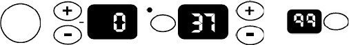
THE ELECTRONIC TEMPERATURE CONTROL PANELTHE ELECTRONIC TEMPERATURE CONTROL PANEL
PowerPower
On/OffOn/Off
WarmerWarmer
ColderColder
WarmerWarmer
ColderColder
FFRREEEEZZEER R RREEFFRRIIGGEERRAATTOORR
WAWATER TER FILTERFILTER
PERCENT LEFTPERCENT LEFT
RESETRESET
°
CC
SELECTSELECT
The electronic control monitors the water valve
for total elapsed time and gallons of water
used. The number displayed on the Water
Filter Indicator (WFI) is the percentage of filter
usage remaining.
The numeric display can be set for Fahrenheit
or Celsius and displays the actual tempera-
tures. The display range for the refrigerator is
from 27
°
F to 70
°
F. The normal freezer display
range is from –9°F to 70°F. Temperatures
above or below these limits will be displayed at
the corresponding temperature limit. During
Max Cool, the freezer display will read –10
°
F,
and the refrigerator will read 32°F.
The display will show the temperature setting
any time the actual temperature is within±6°F
of the customer setting. This will prevent con-
cern over temperature fluctuations when the
doors are opened. Press the temperature ad-
justment key to view the current temperature
setting, or to change the setting. When the
temperature adjustment key is used to change
the temperature setting, the display will brighten
for 5 seconds.
Available features include:
•Water Filter Indicator
•Max Cool
•Over-Temperature Alarm
•Holiday Mode
Contents Summary of Kitchenaid Kssc36Fkb00
- Page 1KAR-11 TECHNICAL EDUCATION MODELS: KSSC36FKB00 KSSS42FKB00 KSSC36FKS00 KSSS42FKT00 KSSC36QKS00 KSSS42FKW00 KSSC42FKB00 KSSS42FKX00 KSSC42FKS00 KSSS42QKB00 KSSC42QKS00 KSSS42QKT00 KSSC48FKB00 KSSS42QKW00 KSSC48FKS00 KSSS42QKX00 KSSC48QKS00 KSSS48FKB00 KSSP36QKS00 KSSS48FKT00 KSSP42QKS00 KSSS48FKW00 K
- Page 2FORWARD This KitchenAid Job Aid, 2001 K Model Built-In Side-By-Side Refrigerator With Variable Capacity Compressor (Part No. 4317326A), provides the technician with informat ion on the installation and service of the Built-In Side-By-Side Refrigerator. It is to be used as atraining Job Aid and Servi
- Page 3TABLE OF CONTENTS Page GENERAL ............................................................................................................................... 1-1 Safety First......................................................................................................................... 1-1
- Page 4Page DIAGNOSIS & TROUBLESHOOTING ................................................................................... 6-1 Diagnosis ........................................................................................................................... 6-1 Pre-Diagnostics Checks ..................
- Page 5GENERAL SAFETY FIRST Your safety and the safety of others is very important. We have provided many important safety messages in this Job Aid and on the appliance. Always read and obey all safety messages. This is the safety alert symbol. This symbol alerts you to hazards that can kill or hurt you an
- Page 6ELECTROSTATIC DISCHARGE (ESD) SENSITIVE ELECTRONICS ESD problems are present everywhere. ESD may damage or weaken the electronic control assembly. The new control assembly may ap- pear to work well after repair is finished, but failure may occur at a later date due to ESD Electrical Shock Hazard str
- Page 7MODEL & SERIAL NUMBER DESIGNATIONS MODEL NUMBER MODENLUMBER KS SS4 2 Q K X 0 0 PRODUCT GROUP K = KitchenAid Brand PRODUCT IDENTIFICATION BR = Bottom Mount Right Hand Hinge BL = Bottom Mount Left Hand Hinge SS = Side-By-Side Built-In MERCHANDISING SCHEME/SERIES C = Wrap Around Stainless Steel P = Fac
- Page 8MODEL & SERIAL NUMBER LABEL AND TECH SHEET LOCATIONS The Model/Serial Number Label and Tech Sheet locations are shown below. Model & Serial Number Location (Freezer Compartment) Tech Sheet Location (On Unit Compartment Cover) 1-4�
- Page 9SPECIFICATIONS Model Number KSSC36FKB KS S C 3 6 F KS KSSC 36 Q KS Model Description Black Architect Series - Non-Disp. Architect Series - Non-Dispenser with Stainless Steel Architect Series - with water filter water filter Disp. - with water filter Size-Configuration 36" 36" 36" Refrigerator Volume
- Page 10Model Number K SSS3 6 F K B KSSS3 6 F K T K SSS3 6 F K W Black Trim -Custom Panels Required- Biscuit Trim -Custom Panels Required- White Trim-Non-Dispenser-Custom Model Description Non-Dispenser with water filter Non-Dispenser with water filter Panels Required with water filter Size-Configuration 36
- Page 11Model Number KSSS42QKB KS S S4 2 Q KT KSSS42QKW Model Description KitchenAid Black Dispenser KitchenAid Biscuit KitchenAid White Water Filter Water with Filter with Water Filter Size-Configuration 42"SidebySide 42"SidebySide 42"SidebySide RefrigeratorVolume (Cu Ft) 15.7 15.7 15.7 Freezer Volume Ft)
- Page 12KITCHENAID® BUILT-IN REFRIGERATOR WARRANTY TWO-YEAR FULL WARRANTY ON REFRIGERATOR For two years from the date of installation, when this refrigerator (excluding the water filter cartridges) is operated and maintained according to instructions attached to or furnished with the product, KitchenAid wil
- Page 13INSTALLATION INFORMATION PRODUCT DIMENSIONS Front View Side View 1 251/8" (64 cm) 231/2" (60 cm) 2 24" 831/8" (61 cm) (211 cm) 831/8" (211 cm)* A 3 (see chart following) Width of Refrigerator 31/2" (9 cm)* Model WidthA(asshownabove) 36 (91 cm) " 36-1/4 (92 cm) " 1. 25-1/8" (64 cm) dimension is to fr
- Page 14Openings The water shutoff should be located in the base The built-in refrigerator can be installed into a cabinet on either side of the refrigerator. The recessed opening in the cabinets, or at the end right side is recommended. The access hole through the right cabinet must be within 1/2 ″ of cabi
- Page 15WATER SUPPLY REQUIREMENTS • Locate the boards so the bottom surface of ″ the boards are 84 (213 cm) from the floor. IMPORTANT: • During installation, raise the refrigerator up • If you turn the refrigerator on before the ″ so there is 1/4 (6.4 mm) maximum between water line is connected, turn the ic
- Page 16LOWERING THE LEVELING LEGS 2. Use the leveling bolts to adjust the leveling legs until the refrigerator is level from left All four leveling legs must contact the floor to to right. support and stabilize the full weight of the refrigerator. Rollers are for moving the refrig- erator, and not for perm
- Page 173. ″ Loosen the four 3/8 hex-head screws on 2. Use an allen wrench and remove the door top of both door hinges. stop screw and locking plate from the 1 bottom door hinge. 1. Mounting screws 3. Use an open-end wrench and turn the bushing, located under the bottom of the hinge, to the left to raise th
- Page 18Door Swing Adjustment 2. Move the door to the desired open posi- 1. Open the refrigerator and freezer doors tion, and then reinstall the door stop screw and make sure that they open freely. If a at one of the three holes that is closest to door opens too wide, remove the door the desired position. s
- Page 19THEORY OF OPERATION Warmer Warmer F REEZ ER REFRI G ERATOR WATER FILTER Power °C RESET SELECT On/Off PERCENT LEFT Colder Colder THE ELECTRONIC TEMPERATURE CONTROL PANEL OVERVIEW The electronic control monitors the water valve for total elapsed time and gallons of water The KitchenAid Built-In Refrig
- Page 20TEMPERATURE CONTROL Freezer Temperature Control — Temperature Decreasing The electronic control checks the resistance of the thermistors, and compares it to both the When the freezer temperature begins to de- customer temperature settings and the last crease, the process will reverse. Thecompres- th
- Page 21COMPRESSOR COMPRESSOR PROTECTION The main control board supplies a 5 vdc, peak- To protect the compressor and maintain effi- to-peak square wave, at 54 to 150 Hz, to the ciency, minimum compressor off time is pro- inverter board. A standard VOM will read ap- grammed into the control. When the compre
- Page 22The refrigerator temperature determines the POWER INTERRUPTION opening of the air door. When the refrigerator After a power interruption, the following events requires cooling, if the evaporator fan motor is will occur: already running for the freezer, the air door partially opens, and then adjusts,
- Page 23Freezer Thermistor MAX COOL MODE If the control senses an open or a shorted ther- Max Cool changes the refrigerator tempera- mistor, the compressor and the evaporator fan ture setting to 32 F (0 C) and the freezer to ° ° motor will begin to operate on a timed on and –10 F (–23 C) for 24 hours. Durin
- Page 24In the Holiday Mode the following occurs: freezer temperature exceeds 15 F (–9 C) for ° ° • Temperature selections remain at the cur- over 1-1/2 hours. The appropriate temperature rent setting, but are not displayed. display flashes to show the user which com- partment is effected. The alarm stops i
- Page 25AIR CIRCULATION It is important not to block any of the vents with food items. If the vents are blocked, airflow will In order to ensure the proper refrigerator and be restricted, and the temperature manage- freezer compartment temperatures, air must ment system will not function properly. be able t
- Page 26SEALED SYSTEM SCHEMATIC EVAPORATOR CONDENSATE PAN HEAT LOOP MULLION HEAT LOOP FILTER-DRIER CAPILLARY TUBE HEAT EXCHANGER SUCTIONLINE DISCHARGE CONDENSER COMPRESSOR 3-8�
- Page 27COMPONENT ACCESS This section instructs you on how to service each component inside the refrigerator/freezer. The components and their locations are shown below. COMPONENT LOCATIONS Condenser Fan Motor Compressor Main Control Filter/Drier Board Assembly Inverter Assembly Freezer Door Refrigerator Do
- Page 28REMOVING THE UNIT COMPARTMENT COVER 4. Remove the two hex-head screws from the air diverter and remove the diverter. 5. Remove the nine hex-head screws from the unit compartment front cover, and pull the cover forward out of the way. Unit Compartment Front Cover Electrical Shock Hazard Disconnect po
- Page 29METHOD A METHOD B 1. Pull the refrigerator out of its mounting 1. Remove the left and right hex-head screws location so you can access the rear of the (one on each side) from the front corners unit. of the unit compartment cover (see the top 2. Remove the left and right hex-head screws left photo).
- Page 30REMOVING A DOOR SWITCH, THE POWER SWITCH, THE INVERTER ASSEMBLY, AND THE MAIN CONTROL BOARD ASSEMBLY b) Remove the two hex-head screws from the door switch cover and remove the cover. Door Switch Cover Screw (1 of 2) Electrical Shock Hazard Disconnect power before servicing. Replace all panels befor
- Page 314. To remove a door switch (Revised De- b) Remove the four wire connectors from sign): the power switch terminals. a) Remove the two hex-head screws from c) Press in on the locking arms and push the door switch cover and remove the the switch out of the cover opening. cover. Door Switch Cover Screws
- Page 32d) Pull the inverter assembly forward so it f) Remove the compressor terminal cover. is free of the retaining bracket, rotate To remove the cover, insert a flat-bladed the box so you can access the rear screwdriver into the top slot, push down mounting screw, and remove thescrew. on the screwdriver
- Page 33c) Remove the wire connectors from the main control board assembly. Wire Connectors Electrical Shock Hazard Connect green ground wire to ground screw. Failure to do so can result in death or electrical shock. REASSEMBLY NOTE: Be sure to reconnect the green ground wires; one to the compressor termina
- Page 34REMOVING THE CONDENSER FAN MOTOR Electrical Shock Hazard Wire Connector Disconnect power before servicing. Replace all panels before operating. Failure to do so can result in death or Fan Motor Bracket Screws electrical shock. 6. Lay the condenser fan motor on a work surface with the fan blade facin
- Page 35REMOVING THE COMPRESSOR AND FILTER/DRIER 6. Loosen the strain relief screw from the compressor terminal cover and remove the wire. Ground Wire & 3-Pin Lead Electrical Shock Hazard Disconnect power before servicing. Replace all panels before operating. Failure to do so can result in death or electric
- Page 36REMOVING THE BIMETAL, THE EVAPORATOR FAN MOTOR, THE DEFROST HEATER, AND THE EVAPORATOR 6. Lift and unhook the two evaporator cover tabs, then lower the cover until the top edge clears the air duct, and slide the cover up and out of the freezer. Electrical Shock Hazard Disconnect power before servici
- Page 378. To remove the evaporator fan motor: 9. To remove the defrost heater: a) Pull the fan blade off the motor shaft. a) Remove the two hex-head screws from b) Unclip the motor. the evaporator fan motor shroud. c) Disconnect the wire connector from the b) Lift the evaporator fan motor shroud terminals.
- Page 38f) Remove the hex-head screws from the i) Bend the two hangers at the bottom of right evaporator cover mounting bracket the evaporator. and remove the bracket. Be careful not to drop the screws down the drain hole at the bottom of the liner. Cover the hole with a cloth. Right Evaporator Cover Mounti
- Page 3910. To remove the evaporator: REASSEMBLY NOTES: a) Remove the defrost heater from the 1. The evaporator fan motor shroud has a evaporator (see pages 4-11 & 4-12). foam insert on each side. Note the position b) Access the sealed system and dis- of these inserts in the photo and reinstall charge the r
- Page 40REMOVING THE TOUCH/DISPLAY BOARD & THE MOTORIZED AIR DOOR b) Disconnect the two wire connectors from the touch control assembly and remove the assembly from the refrig- erator. Wire Connectors Electrical Shock Hazard Disconnect power before servicing. Replace all panels before operating. Failure to
- Page 414. To remove the motorized air door: c) Disconnect the wire connector from the a) Remove the hex-head screws from the motorized air door and remove it. RE- motorized air door cover and remove ASSEMBLY NOTE: Be sure to position the cover. the motorized air door with the motor and wires as shown in th
- Page 42REMOVING THE ICE MAKER AND THE AUGER MOTOR & CRUSH/CUBE SOLENOID 3. To remove the ice maker: a) Remove the bottom screw from the ice maker bracket. Electrical Shock Hazard Disconnect power before servicing. Replace all panels before operating. Failure to do so can result in death or electrical shock
- Page 434. To remove the auger motor or crush/ d) To remove the auger, unscrew the drive cube solenoid: coupler (left-hand threads) and remove a) Remove the light shield and the bulb it from the motor shaft. from the socket. e) Remove the three auger motor hex- b) Remove the four hex-head screws from head s
- Page 44REMOVING A THERMISTOR 3. Remove the hex-head screw from the thermistor cover. Pull the cover forward at the screw end, and unhook the tab from the slot at the other end of the thermistor cover. Screw Electrical Shock Hazard Disconnect power before servicing. Replace all panels before operating. Refr
- Page 45REMOVING A LIGHT SOCKET 3. Remove the light shield. 4. Remove the bulb from the socket. 5. Grasp the light socket by the rounded portion and pull out on the narrow end, while pressing the locking arm (see the photo below) with a screwdriver blade. Pull out on the socket until it disengages Electrica
- Page 46REMOVING THE WATER RESERVOIR 3. Use the leveling screws and lower the refrigerator onto the four rollers. Leveling Screws Rear Front Electrical Shock Hazard Disconnect power before servicing. Replace all panels before operating. Failure to do so can result in death or electrical shock. NOTE: Sharp e
- Page 475. Unhook the front edge of the drip pan and 9. Reach under the front of the refrigerator pull it out the front of the refrigerator. and remove the water reservoir outlet tub- ing nut from the water valve and remove Unhook Front the nut from the end of the tubing. Drip Pan 6. Use a putty knife, slid
- Page 48REMOVING THE WATER VALVE 5. Disconnect the 1/2 ″ nut from the water valve inlet. 6. Remove the two hex-head mounting screws from the water valve mounting bracket. Water Valve Bracket Screws Electrical Shock Hazard Water Valve Inlet Tubing Disconnect power before servicing. Replace all panels before
- Page 49REMOVING THE WATER & ICE DISPENSER c) Bow the front panel out at the center and remove it from the top and bottom channels of the water & ice dispenser. Top Channel Electrical Shock Hazard Disconnect power before servicing. Replace all panels before operating. Failure to do so can result in death or
- Page 50c) Repeat the previous step for the other c) Disconnect the three wire connectors corner of the front panel. and remove the subpanel. d) Pull the bottom of the front panel out 2 Wire Connectors and then down to remove it from the dispenser. 5. To remove the dispenser: a) Disconnect the front panel w
- Page 51REMOVING A DOOR GASKET 5. Starting at the top of the door, install the new door gasket by sliding the lip of the gasket under the metal retaining strip. 6. Tighten the top of the metal retaining strip just enough to hold the gasket in place. 7. Starting at the center of the gasket on the right side,
- Page 52REMOVING THE FREEZER OR REFRIGERATOR DOOR b) Use the leveling screws and lower the refrigerator onto the four rollers. Leveling Screws Rear Front Electrical Shock Hazard Disconnect power before servicing. Replace all panels before operating. Failure to do so can result in death or electrical shock.
- Page 53d) Disconnect the water & ice dispenser g) Disconnect the water reservoir tubing electrical harness connector at the back nut at the union and remove the nut of the refrigerator. from the end of the tubing. Water Reservoir Union Nut Water & Ice Dispenser Electrical Harness Connector Water & Ice Disp
- Page 544. Remove the door switch & bracket for the NOTE: The door spring will remain under slight refrigerator or freezer door (see page 4-4 tension when the door is closed. for the procedure). 6. Use a pair of pliers and lift the end of the 5. With the door closed, remove the hex- linkage off the square p
- Page 55COMPONENT TESTING Before testing any of the components, perform • Check all connections before replacing com- the following checks: ponents, looking for broken or loose wires, • The most common cause for control failure is failed terminals, or wires not pressed into corrosion on connectors. Therefor
- Page 56Electrical Shock Hazard Disconnect power before servicing. Replace all panels before operating. Failure to do so can result in death or electrical shock. EVAPORATOR FAN MOTOR CONDENSER FAN MOTOR 1234 Refer to page 4-10 for the procedure for servic- 1234 ing the evaporator fan motor. 1. Run the diagn
- Page 57Electrical Shock Hazard Disconnect power before servicing. Replace all panels before operating. Failure to do so can result in death or electrical shock. COMPRESSOR & INVERTER Pins Refer to pages 4-4 and 4-9 for the procedures • If the 3 to 6 volts DC is present at the for servicing the inverter and
- Page 58Electrical Shock Hazard Disconnect power before servicing. Replace all panels before operating. Failure to do so can result in death or electrical shock. MOTORIZED AIR DOOR DEFROST HEATER & BIMETAL Refer to page 4-14 for the procedure for servic- Refer to page 4-10 for the procedure for servic- ing
- Page 59Electrical Shock Hazard Disconnect power before servicing. Replace all panels before operating. Failure to do so can result in death or electrical shock. MAIN CONTROL BOARD Refer to page 4-4 for the procedure for servicing the main control board. NOTE: See the chart for the main control board test s
- Page 60Electrical Shock Hazard Disconnect power before servicing. Replace all panels before operating. Failure to do so can result in death or electrical shock. CRUSH/CUBE SOLENOID ICE MAKER AUGER MOTOR Refer to page 4-16 for the procedure for servic- ing the crush/cube solenoid. Refer to page 4-16 for the
- Page 61Electrical Shock Hazard Disconnect power before servicing. Replace all panels before operating. Failure to do so can result in death or electrical shock. WATER VALVE SOLENOID DOOR SWITCH Refer to page 4-22 for the procedure for servic- ing the water valve. 1. Unplug the refrigerator or disconnect th
- Page 62— NOTES — 5-8
- Page 63DIAGNOSIS & TROUBLESHOOTING DIAGNOSIS Warmer Warmer F R E E ZE R R E F R I G E R ATOR WATER FILTER Power ° C RESET SELECT On/Off PERCENT LEFT Colder Colder PRE-DIAGNOSTICS CHECKS Both the Power On/Off and the Water Filter • Confirm the refrigerator and freezer tem- Reset keys must be functional. The
- Page 64DIAGNOSTICS CHART Step ComponentTested Result* Comment 01 Thermistor is within normal range. 01 FreezerThermistor 02 Thermistor is open or less than –20 F.° 03 Thermistor is shorted or greater than 115 F. ° 01 Thermistor is within normal range. 02 Refrigerator Thermistor 02 Thermistor is open or les
- Page 65TROUBLESHOOTING CHART PROBLEM POSSIBLECAUSE TESTPROCEDURE-ACTION No DC control voltage from main See "Component Testing" section for main PCB test procedure. PCB to the inverter board. Condenser fan runs Control voltage wires loose or but the compressor Check connections and repair as needed. revers
- Page 66— NOTES — 6-4
- Page 67WIRING DIAGRAMS & STRIPCIRCUITS WIRING DIAGRAM—BOTTOM MOUNT P5 P7 P6 P4 P3 P2 7-1
- Page 68WIRING DIAGRAM—SIDE-BY-SIDE MODELS P5 P7 P6 P4 P3 P2 OPTIONAL - DISPENSER MODELS ONLY 7-2
- Page 69STRIP CIRCUITS COOLING CIRCUITS COMPRESSOR COMPRESSOR INVERTER BOARD WH POWER POWER ON/OFF ON/OFF RD BK L1 RD/WH N P7-8 P7-3 P5-2 ELECTRONIC P5-3 CONTROL BOARD THERMISTOR CONDENSER FAN MOTOR CONDENSER POWER POWER ON/OFF FAN MOTOR ON/OFF BK P5-2 ELECTRONIC P6-1 WH/RD WH L1 CONTROL N BOARD 7-3�
- Page 70EVAPORATOR FAN MOTOR POWER POWER ON/OFF ON/OFF BK P5-2 ELECTRONIC CONTROL P5-3 WH L1 N BOARD P7-4 P7-5 P7-9 P7-10 YL/BU YL/RD WH/VT YL/BK YL WH EVAPORATOR FAN MOTOR RD BU DEFROST CYCLE DEFROST HEATER POWER POWER BIMETAL ON/OFF DEFROST ON/OFF HEATER BK P5-2 ELECTRONIC PK P6-4 L1 CONTROL N BOARD ELECT
- Page 71REFRIGERATOR LIGHT POWER POWER ON/OFF ON/OFF DOOR SWITCH BK P4-1 ELECTRONIC WH/TN L1 CONTROL N BOARD FREEZER LIGHT POWER DOOR SWITCH POWER ON/OFF 3 ON/OFF BK P4-2 ELECTRONIC WH/TN L1 CONTROL N 1 2 BOARD 7-5�
- Page 72— NOTES — 7-6
- Page 73— NOTES — 7-7
- Page 74— NOTES — 7-8
- Page 75PRODUCT SPECIFICATIONS AND WARRANTY INFORMATION SOURCES IN THE UNITED STATES: FOR PRODUCT SPECIFICATIONS AND WARRANTY INFORMATION CALL: FOR WHIRLPOOL PRODUCTS: 1-800-253-1301 FOR KITCHENAID PRODUCTS: 1-800-422-1230 FOR ROPER PRODUCTS: 1-800-447-6737 FOR TECHNICAL ASSISTANCE WHILE AT THE CUSTOMER’S H
- Page 76
- Page 77