Lg Lfx31945 Page 19
Workshop Manuals
- 19 -
3-22 CAUTION : Sealed System Repair
Before making a sealed system repair : Start with the power cord unplugged from the outlet. Plug in the power cord and
between 6 and 12 seconds after it has been pugged in, unplug it from the power source. this will allow both sides of the 3
way valve to be opened to allow for proper evacuation.
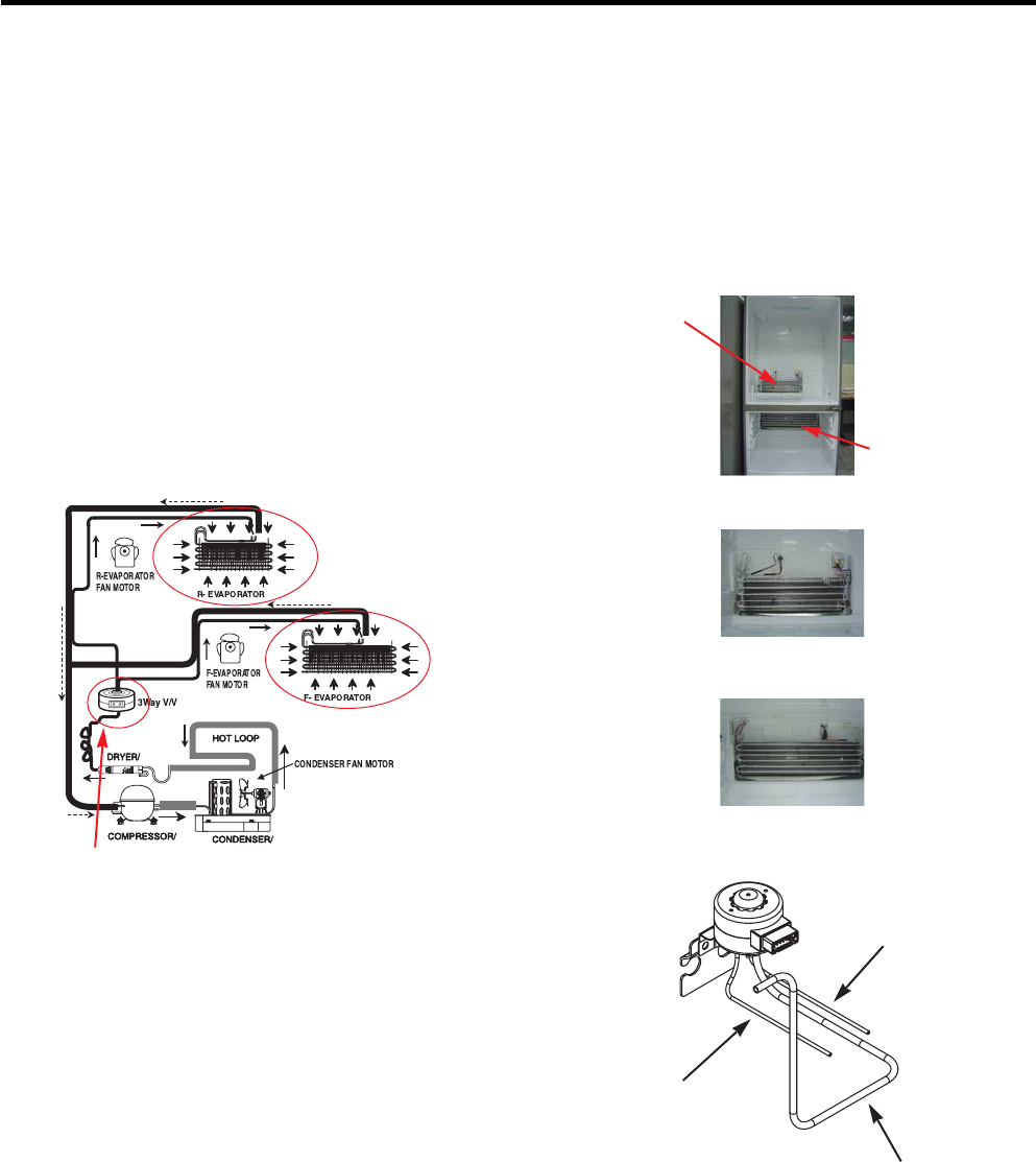
3-23 Way Valve Service
Whole picture of refrigerator
R-Evaporator
F-Evaporator
■ The 3 way valve has plastic parts inside, so always wrap
it with a wet cloth before servicing when using a torch.
1) Always replace the 3 way valve if there is a leak at any
one of the 3 tubes coming from it.
2) Service in replacement of valve (valve failure) Perform
service in the same method as above.
Note : To service sealed system, follow the directions in “3-22”and “3-23”above.Then service is the same as a single
evaporator system.
3 way valve
To Freezer(Refrigerant outlet)
Dryer Side(Refrigerant Inlet)
To Fresh Food
(Refrigerant outlet)
R-Evaporator
F-Evaporator
3 Way Valve
R-Evaporator
F-Evaporator
Contents Summary of Lg Lfx31945
- Page 1REFRIGERATOR SERVICE MANUAL CAUTION BEFORE SERVICING THE UNIT, READ THE SAFETY PRECAUTIONS IN THIS MANUAL. MODEL : LFX31945** COLOR : STAINLESS(ST)�
- Page 2BLY ................................................................................................................................................................ 5- G AND REPLACING REFRIGERATOR DOORS ............................................................................................. 5 .
- Page 3S SPECIFICATIONS ITEMS SPECIFICATIONS Side Rounded VEGETABLE TRAY Clear Drawer Type inches) 35 3/4 X 30 1/4 X 70 1/4 (WXDXH) 31cu.ft. COMPRESSOR Linear pounds) 158kg (348lb) EVAPORATOR Fin Tube Type TEM Fan Cooling CONDENSER Spiral Condenser E CONTROL Micom Control REFRIGERANT R-134a (135 g) SYSTEM
- Page 4shelf The refrigerator LED interior lamps compartment shelves The interior lamps light up the are adjustable to allow inside of the refrigerator. flexibility for storage needs. Preserve large er size food or containers. filter purifies Grab-N-Go Case The convenience of a "soft cool" storage area and
- Page 5Refrigerator Door N: Before you begin, unplug the refrigerator. Remove food and bins from doors. r -FIG. 2 ct water supply tube by pushing back on the disconnect ring (3).-FIG. 1 or. Loosen top hinge cover screw (1). ip screwdriver to pry back hooks on front underside of cover (2). Lift up cover. ct
- Page 6moval Insert and press gasket into channels at doorliner. screws. up carefully. ● Mullion Replacement 1. Connect wire harness. t wire harness. 2. Insert mullion into channel. Insert the mullion into channel at door as shown below. et Removal sket gasket from gasket channel at doorliner as 3. Assembl
- Page 7frigerator doors is uneven, follow the 1. Remove the freezer drawer. ow to align the doors: 2. Remove the plastic guide for slides on left side by g legs (CCW) to raise or (CW) to lower the unscrewing phillips head screws. ont of the refrigerator by using flat blade 3. Remove the grille assembly by
- Page 8Defrost Control assembly consists of Defrost Sensor and he plastic guide for slides on left side by FUSE-M. g phillips head screws. The Defrost Sensor works to defrost automatically. It is e cover sensor to disassemble by using tools attached to the metal side of the Evaporator and senses its he fig
- Page 9rator, or disconnect power at the circuit 1. Unplug refrigerator power cord from electric outlet. 2. Put flat screwdriver into sevice hole and remove cover of move top shelf or shelves. refrigerator light. ator Compartment Lamp crews. nds with your both hands and pull it o remove it. 3. Remove the L
- Page 10gerator power cord from electric outlet. 1. Remove 2 screws and guide rail. frigerator door to need diassembly. wdriver into service hole, remove the cover LED LAMP. 2. Remove the upper and lower Caps by using a flat screwdriver and remove 2 screws as shown figure. LED assembly from connector. 3. Di
- Page 111) Remove the 1 screw holding the lever. 2) Remove the spring from the hook. 3) Push and pull on the tab to remove. drain 2) Holding the inner side of the dispenser pull Button Lever forward to remove. 3-11 WATER BUTTON ASSMEBLY 1) Remove screws. 2) Grasp the Button assembly and lift. Button Lever n
- Page 12crews as shown. properly. ottom of motor cover assembly and pull 3-14 SUB PCB FOR WORKING DISPENSER 1) Disconnect the wire harness. 2) Remove 1 screw from PCB and replace with new PCB. wire harness from wall of compartment. In-door motor - 12 -�
- Page 13e Housing of the Cap Duct Motor. screws to disassemble the motor. cing the motor, check the position of the door link for proper fit. Duct Door Link Cap Duct Motor NG Position ws. g aside. - 13 -�
- Page 14ndles, as shown. 1) Insert the Ice Bin, slightly tilting to avoid touching the Icemaker. (Especially, Ice-Detecting Sensor) lightly as shown. bin slowly. - 14 -�
- Page 15Steps to Remove the freezer door. Step 2) Remove the lower basket. ve the two screws from the guide rails (one Step 4) Removal of the freezer door is done by l ifting clear ach side). of the rail support. Fully extend both rails. ve only 1 screw of gearice, and disassemble Step 6) Remove 2 screws of
- Page 16both side of supporter cover tv into Step 2) ① Assemble a bar and gear ice with screw. ctor rails, and then screw them. ② Push the otherside of the gear to inside of the bar. ar ice assembled with the bar by screw into Step 4) Insert opposite gear ice into connector rail and ctor rail’s hole. screw
- Page 17water to unit. Remove the waterline from the 1) Remove screws for the Drain Pipe Assembly and the 1 connected to the Motor Cover. MOTOR COVER er and 1 screw from the valve. 2) Separate the Fan Assembly and Motor, turn counter clockwise to remove from the motor shaft. anical Cover FAN ASSEMBLY MOTOR
- Page 18ade screwdriver to push the tab in on the left rail and push the tab on the right rail in with your finger. bs have been pushed in, you can lift the tray up and out. ls out to the full extension and insert the insert the back of the tray into both rails. Then set the front of the rail and push it un
- Page 19a sealed system repair : Start with the power cord unplugged from the outlet. Plug in the power cord and 12 seconds after it has been pugged in, unplug it from the power source. this will allow both sides of the 3 e opened to allow for proper evacuation. lve Service Whole picture of refrigerator alv
- Page 20ASSEMBLY, HOME BAR 3-24-2 DOOR BASKET OF HOME BAR DOOR Bar is removable for easy cleaning and The Door Baskets are removable for easy cleaning and adjustment. e the Home Bar, Slopingly lifts the Home Bar 1. To remove the Door Baskets, simply lifts the Door straight out. Baskets up and pulls straight
- Page 21ront is removable for easy cleaning and adjustment. e the Cover Front, simply lifts the basket doorr up and pulls slopingly out. wo screws of The Cover Front and pull slopingly straight out. eplace the Cover Front and basket door, Slide them in above desired support and push down until them lace. !
- Page 22Screw of Right Hinge Cover. 2. Remove two Wire connectors. inge lever clockwise. 4. Separate the Home Bar. OR FOAM ASSEMBLY, ATOR up and out. - 22 -�
- Page 23ews on hinge assebmbly, Upper 2. Separate the Cap,decor on the frame door. ok of door switch, 4. Remove a wire connector for change. s it outward. - 23 -�
- Page 24screw located on the top of hinge. 2. Remove the cap hinge(upper) Cap Hinge(Upper) bar by pushing it up from the 4. Pull out the bar thought the top hinge. ugh the SVC hole (bottom hinge). SVC Hole e Cover. - 24 -�
- Page 25Since linear Comp conducts linear reciprocating motion, we have protection logic for compressor, motor and PCB or intakes low temperature and low pressure as the below. vaporator of the refrigerator and compresses -temperature and high-pressure gas. It then - Stroke Trip s to the condenser. During t
- Page 26- 26 �
- Page 27When checking Resistance values, make sure to turn off the power, and wait for the voltage to discharge. FRESH AIR FIL TER 3 hours after the error : Press the Ice Plus button and Freezer button simultaneously s after the error : All errors, except for "Er rt", "Er SS", (except for Icing sensor)", "E
- Page 28MFG Picture CON5 CON6 CON7 30936 .01~) CON3 CON2 CON1 - 28 -�
- Page 29o Picture y PCB 29554 .03~) PCB 070709 .01~) - 29 -�
- Page 30Checking flow Result & SVC Action Check for a loose connection. Check the Blue/White to Blue/White. Result SVC Action 0Ω Short Change the sensor OFF Open Replace the refrigerator Check the Temp and Other Normal resistance (Table-1)
(1) To (2) Result -22°F / -30°C 40 ㏀ -1 - Page 31Checking flow Result & SVC Action Check for a loose connection. Check the White to White. Result SVC Action 0Ω Short Change the sensor OFF Open Replace the refrigerator Check the Temp and Other Normal resistance (Table-2)
(1) To (2) Result 23°F / -5°C 38 ㏀ 32°F / 0°C 30 - Page 32Checking flow Result & SVC Action Check for a loose connection. Check the Blue to Blue. Result SVC Action 0Ω Short Change the sensor OFF Open Replace the refrigerator Check the Temp and Other Normal resistance (Table-1)
(1) To (2) Result -22°F / -30°C 40 ㏀ -13°F / -25°C - Page 33Checking flow Result & SVC Action Check for a loose connection. Check the Orange to Orange. Result SVC Action 0Ω Short Change the sensor OFF Open Replace the refrigerator Check the Temp and Other Normal resistance (Table-3) Check the Brown to Brown.
(1) To (2) Result 23°F / -5° - Page 34Checking flow Result & SVC Action Check for a loose connection. Check the Orange to Orange. Result SVC Action 0Ω Short Change the sensor OFF Open Replace the refrigerator Check the Temp and Other Normal resistance (Table-3)
Check the Gray to Gray. (1) To (2) Result 23°F / -5°C - Page 35Checking flow Result & SVC Action Check the Door gasket. Part Result SVC Action Check the Defrost control part. 0Ω Go to the 3 Fuse-M Other Change Fuse-M Def’ 34~42 Ω Go to the 3 Heater Change Fuse-M Def’ Def’ Other Heater Heater Go to the 3 Def’ 22 ㏀↑ Sensor OFF Replace product Fuse M nput Test 3 M
- Page 36Checking flow Result & SVC Action Check the Door gasket. Part Result SVC Action Check the Defrost control part. 0Ω Go to the 3 Fuse-M Other Change Fuse-M Def’ 34~42 Ω Go to the 3 Heater Change Fuse-M Def’ Def’ Other Heater Heater Go to the 3 Def’ 22 ㏀↑ Sensor OFF Replace product Fuse M nput Test 3 M
- Page 37Checking flow Result & SVC Action Reset the unit and nput Test 1 Mode. Push the button 1 time) Open the freezer door and Check the air Status SVC Action low. ※ While an error code is displayed, No windy Go to 3 the fan is not working. Windy Go to 4 Check the Fan motor voltage. (3) (2) (1) Point Resu
- Page 38Checking flow Result & SVC Action Reset the unit and nput Test 1 Mode. Push the button 1 time) Open the freezer door and Check the air Status SVC Action low. ※ While an error code is displayed, No windy Go to 3 the fan is not working. Windy Go to 4 Check the Fan motor. Rotate fan using your hand. It
- Page 39Checking flow Result & SVC Action Reset the unit and nput Test 1 Mode. Push the button 1 time) Open the freezer door and Check the air Status SVC Action low. ※ While an error code is displayed, No windy Go to the 3,4 the fan is not working. Windy Go to the 5 Check the Connector. Frozen caused the PC
- Page 40Checking flow Result & SVC Action Reset the unit and nput Test 1 Mode. Push the button 1 time) Check the fan rotating. Status SVC Action ※ While an error code is displayed, No windy Check motor the fan is not working. Windy Go to the 4 Check the Fan motor and surrounding. Rotate fan using your hand.
- Page 41Checking flow Result & SVC Action Check the loose connection. Check the Red to White/Red. Result SVC Action 12 V Go to the 3 Check the Hinge Other (loose connection) CON101 Change the Main PCB
Check the Orange to White/Red. Result SVC Action 0 or 5 V Change the Display PCB Other G - Page 42Checking flow Result & SVC Action Check the loose connection. Check the Black to White. Lever s/w Result SVC Action While pushing the lever S/W) 112 ~ 115 V Go to the 3 Pushing Other Change PCB Not 0~2V Go to the 3 pushing Other Change PCB
Check the RED to White Red. Lever s/w Result SVC Acti - Page 43Checking flow Result & SVC Action Check the loose connection. Check the Sky Blue to White. Lever s/w Result SVC Action While pushing the lever S/W) 112 ~ 115 V Go to the 3 Pushing Other Change PCB Not 0~2V Go to the 3 pushing Other Change PCB
Check the Black to White Red. Lever s/w Result SVC - Page 44Checking flow Result & SVC Action Check the loose connection. Check the Purple to White. Lever s/w Result SVC Action While pushing the lever S/W) 112 ~ 115 V Go to the 3 Pushing Other Change PCB Not 0 ~2 V Go to the 3 pushing Other Change PCB
Check the resistance value. Point Result SVC Actio - Page 45Checking flow Result & SVC Action Check the Freezer door switch. If feel sticky, Change the door s/w. Check the door S/W resistance. Status Result SVC Action 0Ω Go to the 3 Normal not Change door S/W Push Infinity Go to the 3 S/W Other Change door S/W Check the Red/yellow to Pink. Status Result SVC
- Page 46Checking flow Result & SVC Action Check the Refrigerator door switch. If feel sticky, Change the door s/w. Check the door Switch resistance. Status Result SVC Action 0Ω Go to the 3 Normal Other Change door Switch Push Infinity Go to the 3 S/W Other Change door Switch Check the Red/yellow to Pink. St
- Page 47Checking flow Result & SVC Action Check the sensor resistance. Temperature Result 23°F / -5°C 38 ㏀ 32°F / 0°C 30 ㏀ 41°F / 5°C 24 ㏀
50°F / 10°C 19.5 ㏀ 59°F / 15°C 16 ㏀ ※ The sensor is determined by the temperature. For example, 30㏀ indicates 32°F. Reset the unit and nput Test 1 Mode. Push the - Page 48Checking flow Result & SVC Action Check the R Fan motor voltage. 3) (2) (1) Point Result SVC Action (1) ~ (2) Below 12 V Change the PCB (1) ~ (3) 0 or 5 V Change the motor
- 48 -� - Page 49Checking flow Result & SVC Action Check the sensor resistance. (1) To (2) Result -22°F / -30°C 40 ㏀ -13°F / -25°C 30 ㏀ -4°F / -20°C 23 ㏀ 5°F / -15°C 17 ㏀
14°F / -10°C 13 ㏀ ※ The sensor is determined by the temperature. 23°F / -5°C 10 ㏀ For example, 23㏀ indicates -4°F. 32°F / 0°C 8㏀ Reset the - Page 50Checking flow Result & SVC Action Check the Fan motor. Rotate fan using your hand. Point Result SVC Action t feel sticky, change the motor. cause of ice or rust inside of motor). Motor Sticky Change the motor Check the F Fan motor voltage. Point Result SVC Action (1) ~ (2) Below 12 V Change the PCB
- Page 51o make TEST MODE push the test button on the Main PCB, the refrigerator will be enter the TEST MODE. * 1 time : Comp / Damper / All FAN on (All things displayed) * 2 times : Damper closed (22 22 displayed) * 3 times : Forced defrost mode (33 33 displayed) Main PCB remove Terminal Position Assurance
- Page 52TEMP RESISTANCE VOLTAGE -39°F (-40°C) 73.29 ㏀ 4.09 V -30°F (-35°C) 53.63 ㏀ 3.84 V -30°F (-21°C) 39.66 ㏀ 3.55 V -13°F (-25°C) 29.62 ㏀ 3.23 V -4°F (-20°C) 22.33 ㏀ 2.89 V 5°F (-15°C) 16.99 ㏀ 2.56 V 14°F (-10°C) 13.05 ㏀ 2.23 V 23°F (-5°C) 10.10 ㏀ 1.92 V 32°F (0°C) 7.88 ㏀ 1.63 V 41°F (+5°C) 6.19 ㏀ 1.38 V
- Page 53TEMP RESISTANCE VOLTAGE -39°F (-40°C) 225.1 ㏀ 4.48 V -30°F (-35°C) 169.8 ㏀ 4.33 V -30°F (-21°C) 129.3 ㏀ 4.16 V -13°F (-25°C) 99.30 ㏀ 3.95 V -4°F (-20°C) 76.96 ㏀ 3.734 V 5°F (-15°C) 60.13 ㏀ 3.487 V 14°F (-10°C) 47.34 ㏀ 3.22 V 23°F (-5°C) 37.55 ㏀ 2.95 V 32°F (0°C) 30 ㏀ 2.67 V 41°F (+5°C) 24.13 ㏀ 2.40
- Page 54PCB cover Step 2) Check for blinking frequency of LED, PCB is normal, it does not blink next page to find out what actions to take according to how many times LED blink - 54 -�
- Page 55LED operating condition Cause Service guideline 1.After resetting o - time repetiton PCB part power, check if it is defect running normal (piston 2.If the same overrun) symptom arises after on - off - on - on - off - on - on - off repeating the first action, replace PCB 1.After resetting power, chec
- Page 56nding a signal to the fan, the MICOM checks the BLDC fan lock status. If there is no feedback signal from the BLDC fan, motor stops for 10 seconds and then is powered again for 15 . To determine that there is a fan motor malfunction, cess is repeated 3 times. If the fan motor is determined to be e,
- Page 57The controller assembly is made up of two different kinds of parts. The fuse and the sensor. To determine if these parts are defective, check for resistance. The fuse will cut power to the defrost heater at very high temperatures. Set a ohmmeter to the 2 housing pin. Measure the 2 pin connected to F
- Page 58Sheath heater is the part for defrost. All heating wire is connected to only one line. So we can decide part is defective or not when we check the resistance. (1) (2) Set a ohmmeter connect to The housing pins. Measure the pins connected to Sheath Heater. If the ohmmeter indicates (V°øV)/Watt=R is o
- Page 59Sheath heater is the part for defrost. All heating wire is connected to only one line. So we can decide part is defective or not when we check the resistance. (1) (2) Set a ohmmeter connect to The housing pins. Measure the pins connected to Sheath Heater. If the ohmmeter indicates (V°øV)/Watt=R is o
- Page 60The heater is designed for anti-dew on the door. 1 3 2 4 6 5 7 8 9 Test Point Ressult (1) to (2) 2.3 ~ 2.9Ω - 60 -
- Page 61The switch senses if the door is open or closed. - When the door open, lamp on. - When the door open, the switch give information to Micom. When the door open, internal contact operate on and off moving plunger of door switch up and down.
- Page 62- Dispenser DC Motor : When customer push the dispenser button, Pull duct door and abstract from ice bank. (1) (2) Dispensor DC Motor Dispenser DC Motor Test Points Result (1) to (2) 9.9 ~ 12.1Ω - 62 -
- Page 63The motor in the door pushed the ice into the dispenser. < In-door Motor > < In-door Motor > 1 Separate the 1 Separate the housing. housing. 2 Measure the 2 Measure the resistance between resistance between (1) and (2) (1) and (3) (1) (2) (1) (3) Check the resistance between connectors (In-door moto
- Page 64The damper supplies cold air from the freezer to the chill room using the damper plate. The chill room is colder when the damper plate is open. When the damper is closed the chill rooms temperature will rise. < Damper Circuit > 1 Blue 1 Blue 2 Red 3 White 3 White 3 Yellow Check the 1 , 3 < extension
- Page 65The lamp socket connect cover lamp assembly to lamp. The lamp socket fix lamp and unite lamp and cover lamp assembly. The lamp socket supply electric source to lamp also. (1) (2) (3) (4) Check the resistance between connector of housing and connector of lamp socket. It means check whether or not app
- Page 66Flow Sensor (in machine room) Count the water quantity from city water to water filter in refrigerator Flow Sensor (in machine room) Test Points Result Red wire to Black wire 4 ~ 30 kΩ - 66 -
- Page 67Protection Logic TEST 1 Mode Con201 Time>30sec Y Power On PCB OK Disconnect & V≒200 N Replace Driver PCB Check Voltage about 200V past 30second after turn on Comp Ref. Display & sound Refer FC75(A-Inverter) Forced Starting TDC (Full Stroke) Display ON, Buzz 1 time ting LED blink 1 Reset LED blink 1
- Page 68Board located in the PCB case. river is PC board for the compressor. ows the source voltage of the driver PC board. n PCB Cover Step2. Check Driver PCB ocated in machine room. - 68 -�
- Page 69Check to make sure compressor is receiving voltage from IPM - In order to determine whether the compressor is operating normally, check the output voltage during the refrigeration cycle. Multi Tester - After initial power-up, when the compressor begins to operate, wait 10 minutes before checking. A-
- Page 70s once, then repeats (FCT0 Fault: A-Inverter) Protection Logic OFF tecting motor current and voltage error e at point A (Motor Voltage), point B (Motor Current) and Point C (Capacitor n compressor is off. A, B, & C 2.5V ± 0.3V ction Blink 1 time ic (FCT 0) Check B1 k B Out of spec? Y (2.2 - 2.8V) Re
- Page 71link Blink OFF detect locked piston of oil to the cylinder, cylinder or piston damaged and or restricted discharge. ston can also be caused by foreign materials inside the compressor. ressor is forced off and tries to restart within 2.5 minutes. tion Replace Blink 5 times c Compressor (Lock Piston T
- Page 72Blink Blink Blink Blink OFF vent high current due to IPM Short aged IPM (Dead Short) ad short at Point A with a VOM. ressor is forced off and tries to restart in 20 seconds. Blink 7 times A (Lock Piston Trip) Check B5 Y Check IPM Short N Compressor Replace visual inspection Test Doesn’t work Drive P
- Page 73onnection Check Check Process Specifications or Check er off. Step 2. Check capacitor spec. (table1). Step3. Check resistance of point A tep 4. Check wire harness (INF ohm). Step 5. Check resistance at point B. Step 6. Point D. Check Y Resistance Y Check Y Harness Power wiring to Capacitor at Point
- Page 74rotection logic Cycle check with protection logic heck Condenser fan and Freezer fan before performing Check D n, Current trip and stroke trip can be activated by other problems then the driver or compressor. → When process line on compressor is opened, and refrigerant is not expelled High Pressure
- Page 75NG HIGH VOLTAGE PCB cover Step 2) Check for blinking frequency of LED and PCB When compressor is normal, it does not blink : Refer to the next page to find out what actions to take according to how many times LED blink - 75 -�
- Page 761. Please check, Whether PCB Parts connector of defect or compressor is attached o - time repetiton (Stroke Trip) Compress rightly or not. after or power off Connector 2. After the first action, miss You check on normal on - off - on - on - off - on - on - off repeating connecting operation of (Pist
- Page 77T POINTS TO BE CHECKED REMEDY • Is the power cord unplugged from the outlet? • Plug into the outlet. • Check if the power switch is set to OFF. • Set the switch to ON. • Check if the fuse of the power switch is shorted. • Replace the fuse. • Measure the voltage of the power outlet. • If the voltage
- Page 78ooting Chart TEMPERATURE STATE OF STATE OF THE OF THE E REMARKS THE UNIT EVAPORATOR COMPRESSOR IAL Freezer Low flowing sound of A little higher than • Refrigerant level is low due AGE compartment and Refrigerant is heard ambient to a leak. Refrigerator don't and frost forms in temperature. • Normal
- Page 79“Not Cooling” Complaint All components operating, No airflow problems, Not frosted up as a defrost problem problem has been isolated to sealed system area Partial Frost None Pattern? Equalization Equalization Test Test ry Fast Very Slow Very Slow Fast Very Fast fficient Partial Complete pressor Rest
- Page 80Power On Start Position • Adjusts Ice Tray to Start Position with power on. Icemaking • Waits until water becomes ice. Mode For cold air circulation, Ice tray will be on a slightly tilt one hour after ice-making mode begins. Atilt ice tray Ice Tray on a slightly tilt Full Ice means icemaker’s normal
- Page 81aking Mode Mode begins right after the ice tray fills with water. aits until water becomes ice in the ice tray. g sensor checks if the ice bin is full every 2min. est Mode min, since icemaker begun icemaking mode, Icemaker starts to twist the ice tray to drop ices into the Ice bin. ion, at least 1da
- Page 82nit and Ice-detecting sensor Diagnosis er unit and Ice-detecting sensor is programmed to be diagnosed. rocedure step by step to check to see if icemaker and Ice-detecting sensor is working normally. ker Unit Ice-detecting sensor Fill Key aker Unit Diagnosis) y for about 3sec. If the icemaker runs 2
- Page 83e bin from compartment 2. Close the left door 3. Wait for 3min. (Door switch pushed) 4. Freezer door stays open 5. Push the refrigerator button & lock button at the same time. FRESH AIR FIL TER shown on the display after the procedure above, Ice-detecting sensor is normal. shown on the display after
- Page 84ion ppliance is plugged in, it is set to 37°F for Refrigerator and 0°F for freezer. ust the Refrigerator and the Freezer control temperature by pressing the ADJUST button. ower is initially applied or restored after a power failure, it is set to Control temperature Previously. t press any button aft
- Page 85eplacement indicator light for the filter In initial Power On Blinking Classification the dispenser. / Filter RESET needs replacement once six months or of filter. Filter Status ater Filter Icon blinks, you must exchange Display ing the filter, press and hold the Light/Filter ore than 3 seconds. ate
- Page 86motor has high and standard speeds. is used at power-up, for Ultra Ice, and when refrigerator is overloaded. eeds is used for general purposes. cooling speed, the RPM of the freezer fan motor change from normal speed to high. (2700RPM) : Initial power on or load corresponding operation, Ultra Ice. e
- Page 87tarts each time the COMPRESSOR running time Betwee 7~50 hours. wer on or for restoring power, defrosting starts when the compressor running time reaches 4 hours. tops if the sensor temperature reaches 46.4°F(8°C) or more. If the sensor doesn’t reach 46.4°F(8°C) in 1 efrost mode is malfunctioning. (R
- Page 88Use the part number to order part, not the position number. 603C S04 503E 603E 626A 624E 207B 624G 402A S11 503D 624C 500P S04 409D 158A 103B 271B 610F S11 S04 103A S04 207A 402A 282G 610D 406D 120A 409H 628A B01 631C 631A 405E 405J 405K S02 410J 271D 327B S10 145B 145A 404C 405G 405L 120B 313A S11
- Page 89Use the part number to order part, not the position number. 145G 145C 145J 145K S04 131A 249M 136C 136B 133C 249L S04 132Q 145M 136E 134A 133C 145J 145H 132P 237C 136A�
- Page 90Use the part number to order part, not the position number. 141H 142B 141A 142D 142A 141F 141B 141H 141H 141A 141F 141B 141F 141B 141D 154A 161B 151C 161C 151A 151B 161C 146E 162B 145D 162A�
- Page 91Use the part number to order part, not the position number. 231B 233B 207D 241K 235A 250W 232A B06 281H 241K 312F 250D 241B 241K 250D 312G 281B 241B 207C 312B 146F 281H 250C 312E B06 243C 241A 624A 405M 262C 244A 262E 243B 619B 619C 409I 615A 405M 241J 233A 402B 409I 253A 271E 250B 250E 241N WSZ064
- Page 92Use the part number to order part, not the position number. 276A 276G 276F 276I 405A 276B 275A 278C 279A 278D 2C 279K 279L 501D 279B 281A 501A 279C�
- Page 93Use the part number to order part, not the position number. 617A 625A 616G 616G 623B S04 616J 623B 616J 627B 603C S04 S04 627A 619A 603B�
- Page 94Use the part number to order part, not the position number. 630J 630J 612A 630F 630B 630C 600A 611A 607A 630A 630H 630D 606A 630E 630Q 630G�
- Page 958076 MAY., 2013 Printed in Kore�