Samsung Rsh1Dtmh Page 7
Workshop Manuals
7
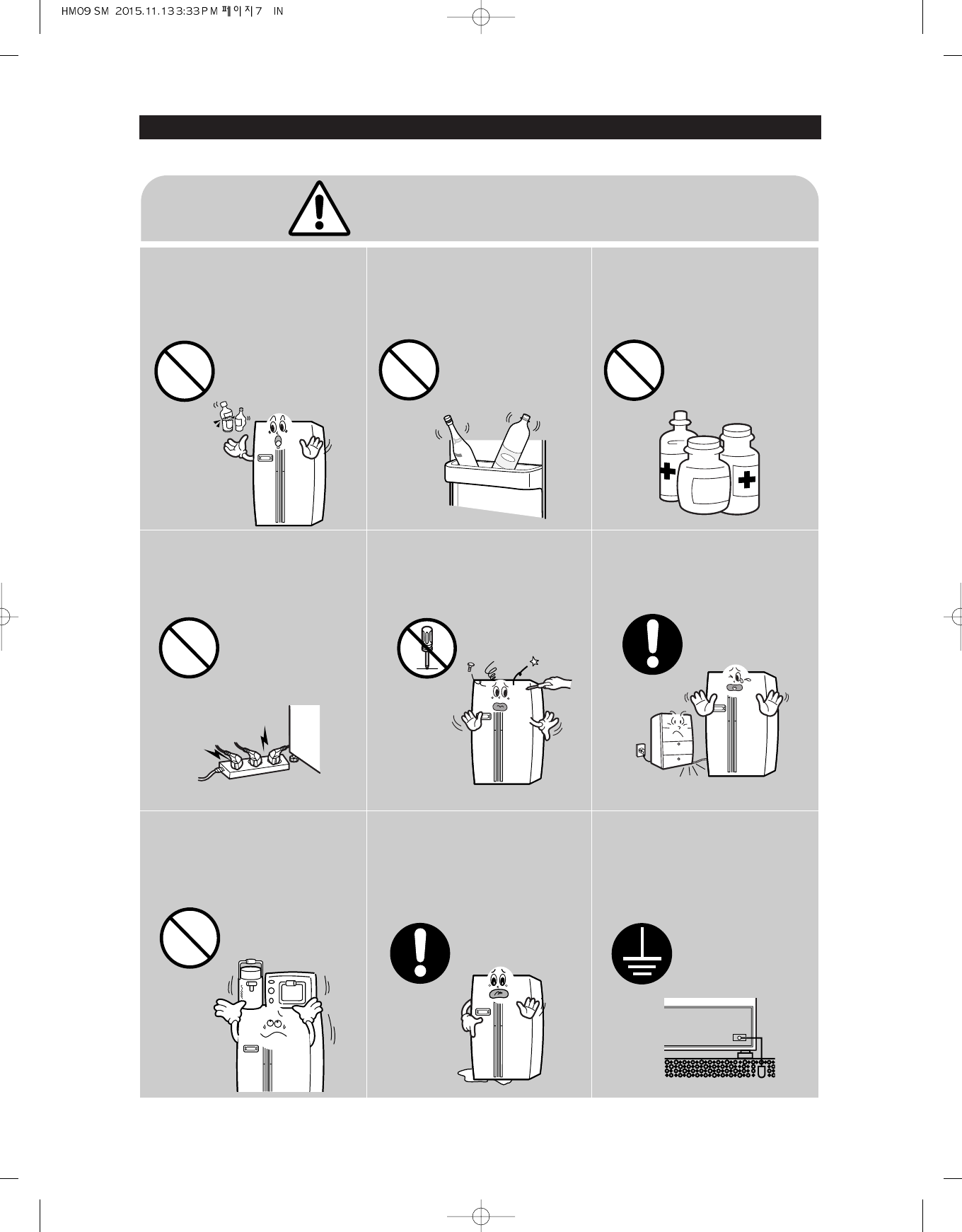
SAFETY WARNINGS
❈
Please ler users know following warnings & cautions in detail.
Do not allow users to put bottles or
kinds of glass in the freezer.
Freezing of the contents may inflict a wound.
Do not allow users to store narrow
and lengthy bottles or foods in a
small multi-purpose room.
It may hurt you when refrigerator door is
opened and closed resulting in falling stuff
down.
Do not allow users to store
pharmaceutical products, scientific
materials, etc., in the refrigerator.
The products which temperature control
should not be stored in the refrigerator.
Do not allow users to store
articles on the product.
Opening or closing the door may cause
things to fall down, with may inflict a
wound.
Prohibition
Prohibition
Prohibition
Prohibition
Warning & Caution
Do not allow users to
disassemble, repair or alter.
It may cause fire or abnormal
operation which leads to injury.
Do not
disassemble
Do not allow users to insert the
power plugs for many products
at the same time.
May cause abnormal generation of
heat or fire.
Prohibition
Do not allow users to bend the
power cord with excessive force
or do not have the power cord
pressed by heavy article.
May cause fire.
Do not allow users to install the
refrigerator in the wet place or
the place which water splashes.
Deterioration of insulation of electric
parts may cause electric shock or fire.
Make sure of the earth.
If earthing is not done, it will cause
breakdown and electric shock.
Earth
Contents Summary of Samsung Rsh1Dtmh
- Page 1REFRIGERATOR SBS TYPE BASIC : RSH1DTMH MODEL NAME (MODEL CODE) : RSJ1Z/K*** RS21H*L** RSJ1Y/J*** RS21H**** RSJ1P/F*** RS23H**** REFRIGERATOR CONTENTS PRECAUTIONS(SAFETY WARNINGS) 5 PRODUCT SPECIFICATIONS 8 DISASSEMBLY & REASSEMBLY 21 TROUBLE SHOOTING 48 PCB DIAGRAM 78 WIRING DIAGRAM 82 SCHEMATIC DIA
- Page 2
- Page 3WARNING IMPORTANT SAFETY NOTICE The service guide is for service men with adequate backgrounds of electrical, electronic, and mechanical experience. Any attempt to repair a major appliance may result in personal injury and property damage. The manufacturer or dealer cannot be responsible for the int
- Page 4Contents 1. PRECAUTIONS(SAFETY WARNINGS) 5 2. PRODUCT SPECIFICATIONS 8 3. DISASSEMBLY & REASSEMBLY 20 4. TROUBLE SHOOTING 46 5. PCB DIAGRAM 78 6. WIRING DIAGRAM 82 7. SCHEMATIC DIAGRAM 94 8. REFERENCE INFORMATION 100 4�
- Page 51. PRECAUTIONS(SAFETY WARNINGS) Upon electronic Control system repair/change, make sure the set unplugged. Be ware of electric shock. Use rated electronic Control equipment. Make sure to check out ModeL name, Rated voltage, Rated current, Operation Temp, etc. Upon repair, make sure that harnesses ar
- Page 6SAFETY WARNINGS Read all instructions before repairing the product and keep to the instructions in order to prevent danger or property damage. CAUTION/WARNING SYMBOLS DISPLAYED SYMBOLS means “Prohibition”. Indicates that a danger of death Warning or serious injury means “Do not disassemble”. exists.
- Page 7SAFETY WARNINGS ❈ Please ler users know following warnings & cautions in detail. Warning & Caution Do not allow users to put bottles or Do not allow users to store narrow Do not allow users to store kinds of glass in the freezer. and lengthy bottles or foods in a pharmaceutical products, scientific
- Page 82. PRODUCT SPECIFICATIONS 2-1) Charcteristics .......................................................................................................9 2-2) Model Specification ............................................................................................10 2-3-1) Electric Parts Specifi
- Page 9PRODUCT SPECIFICATIONS 2-1) Charcteristics Comparison with basic Changed Part Description Basic Current Door HomeBar New design Soft touch type Home Bar Door Display New design Display Insert Convertible New design Convertible New Option Adapted Part Description Image Door Display Ice&Water Type Tou
- Page 10PRODUCT SPECIFICATIONS 2-2) Model Specification This operation instruction covers various models. NOTE The characteristics of your appliance may differ slightly from those described in this manual. - Key features of your new refrigerator Your Samsung Side-By-Side Refrigerator comes equipped with man
- Page 11Brand HERMES LG whirlpool Samsung REMARK Model RS21H**** GRL227SUJA S20ER WW2V RS60K Design - Comparison with competitor PRODUCT SPECIFICATIONS Price (euro¤) 1.199 1.199 1.199 1.323 Superiority Capacity 506L/524L/554L 551L 490L 520L Superiority Contour Contour Flat Door design Flat (Flushed/Hidden H
- Page 12PRODUCT SPECIFICATIONS 2-3-1) Electric Parts Specification(RS21/23H/RSJ1 Series) Items Specification Z/K Y/J P/ F U/D V/B S/N Disp+H/B+ Dispenser+ Model Dispenser+ Cool select Cool select Dispenser Home Bar Basic Home Bar zone zone Defrost- Heater(FRE) Conducting at F Defrosting Sheath Heater 230V 2
- Page 13PRODUCT SPECIFICATIONS 2-3-2) Electric Parts Specification(RS21H** CHINA Inverter Model) Items Specification Z (T/K) V (T/K) S (T/K) Z V S Disp+H/B+ Disp+H/B+ Model Cool select Home Bar Basic Cool select Home Bar Basic zone zone Total 506 554 554 506 554 554 Net Components for Freezer Refrigerator 3
- Page 14PRODUCT SPECIFICATIONS 2-3-3) Electric Parts Specification(RS21/23H/RSJ1 Series - Inverter Model) Items Specification Z Y P U V S Disp+H/B+ Dispenser+ Model Dispenser+ Cool select Cool select Dispenser Home Bar Basic Home Bar zone zone Total 506 506 524 524 554 554 Net Components for Freezer Refrige
- Page 15PRODUCT SPECIFICATIONS 2-3-4) Electric Parts Specification(RS21/23H/RSJ1 - R600a Model) Items Specification K J F D B N Disp+H/B+ Dispenser+ Model Dispenser+ Cool select Cool select Dispenser Home Bar Basic Home Bar zone zone Total 506 506 524 524 554 554 Net Components for Freezer Refrigerator 327
- Page 16PRODUCT SPECIFICATIONS 2-3-5) Electric Parts Specification(RS21/23H/RSJ1 - R134a Model) Items Specification K J F D B N Disp+H/B+ Dispenser+ Model Dispenser+ Cool select Cool select Dispenser Home Bar Basic Home Bar zone zone Total 506 506 524 524 554 554 Net Components for Freezer Refrigerator 327
- Page 17PRODUCT SPECIFICATIONS 2-3-6) Electric Parts Specification(RS21/23H/RSJ1 Series) Items Specification Models RS21/23H/RSJ1 Series Freezing Capacity (4-STAR) Inverter : EU4A5Q-L2XA Model R600a : MK190G-L2U R134a : MK4A5Q-R1U Components for Freezer Compressor Starting type R.S.C.R Oil Charge FREOL -15
- Page 18PRODUCT SPECIFICATIONS 2-4) Dimensions (mm) 511.9 908 "E" 385.9 "F" 55.6 "D" 35 30 1702 1663.5 1779 83 PRODUCT SIZE 18�
- Page 19PRODUCT SPECIFICATIONS 2-5) Optional Material Specification Photograph Part Name Part Code Quantity Remark 19�
- Page 203. DISASSEMBLY & REASSEMBLY 3-1) PRECAUTION....................................................................................................21 3-2) Freezer Display (RS21/23H***) ..........................................................................22 3-2-1) Freezer Display (RS21*L**-TRIMKIT).
- Page 21DISASSEMBLY & REASSEMBLY 3-1) PRECAUTION • Unplug the refrigerator before cleaning and making repairs. • Do not dissemble or repair the refrigerator by yourself. - You run risk of causing a fire, malfunction and/or personal injury. • Remove any foreign matter or dust from the power plug pins. - Othe
- Page 22DISASSEMBLY & REASSEMBLY 3-2) Freezer Display (RS21/23H***) PART NAME FIGURE DESCRIPTION 1. With the Door closed, prepare (+) head screwdriver. 2. Unscrew by turning 1 screw to counterclockwise at bottom. Be careful not to scratch. 3. Pull out Cover Dispenser Assembly. Take care so that hand may not
- Page 23DISASSEMBLY & REASSEMBLY 3-2-1) Freezer Display (RS21*L**-TRIMKIT) PART NAME FIGURE DESCRIPTION 1. With the Door closed, prepare (+) head screwdriver. 2. Unscrew by turning 1 screw to counterclockwise at bottom. Be careful not to scratch. 3. Pull out Cover Dispenser Assembly. Take care so that hand
- Page 24DISASSEMBLY & REASSEMBLY 3-3) Freezer Micro Switch PART NAME FIGURE DESCRIPTION 1. After disassembling Freezer Display, remove 1 screw. 2. Unlock the hook using flat head screwdriver. 3. Pull out Lever Assembly. Freezer Micro S/W 4. Disconnect Micro S/W as shown. Be careful of injury. 24�
- Page 25DISASSEMBLY & REASSEMBLY 3-4) Freezer Door PART NAME FIGURE DESCRIPTION 1. With Door opened, remove 3 screws. 2. Disconnect Valve Fitting with pushing Fixer Valves on both side. 3. With door closed, remove 1 screw on fixing Hinge Cover on the top place. Be careful not to scratch. Freezer Door 4. Dis
- Page 26DISASSEMBLY & REASSEMBLY PART NAME FIGURE DESCRIPTION 7. Remove Upper Hinge with handing Wires Freezer Door 8. Lift up Fridge Door and take out. Be careful of injury. 3-5) Freezer Compartments PART NAME FIGURE DESCRIPTION 1. Lift up Tray Dispenser with grabbing. Tray Be careful not to scratch. Dispe
- Page 27DISASSEMBLY & REASSEMBLY PART NAME FIGURE DESCRIPTION Drawers are designed for storage of fruits, vegetables, and deli items.The drawers are located in the lower portion of the refrigerator. 1. Pull out the drawer as far as it goes. 2. Tilt the drawer up and pull it out until it is removed. Please b
- Page 28DISASSEMBLY & REASSEMBLY PART NAME FIGURE DESCRIPTION Lift Ice Bucket Assembly up and pull out. Be careful not to scratch. Remove 2 screws and pull the Ice Maker Assembldy out with grabbing. Be careful not to scratch. Ice Maker Disconnect the connector and taker out. Be careful not to be damaged on
- Page 29DISASSEMBLY & REASSEMBLY PART NAME FIGURE DESCRIPTION Remove the Lamp Cover with pulling out and lifting up simultaneously. Turn the Bulb to counter clockwise and take out. Be careful of injury. Remove 2 screws and take out the Auger Motor. Be careful not to scratch. Freezer Room Lamp & Auger Motor
- Page 30DISASSEMBLY & REASSEMBLY PART NAME FIGURE DESCRIPTION Remove 4 screws to counter clockwise as shown. Remove the Cover Evap as shown. Be careful not to scratch. Cover Evaporator & Evaporator Sensor Disconnect the connector and take out the on Freezer Cover Evap. Part Disassemble the Fixer Housing wit
- Page 31DISASSEMBLY & REASSEMBLY PART NAME FIGURE DESCRIPTION After remove all Insert Part, remove 1 screw as shown. Be careful not to scratch. Cover Multi on Freezer Part After pulling the upper part of the Cover Multi, Disconnect the 2 connectors as shown. Be careful of injury. Take out the Cover multi wi
- Page 32DISASSEMBLY & REASSEMBLY PART NAME FIGURE DESCRIPTION Remove Grommet located at bottom inner place. Pull the shaft out with pushing down the shaft using flat head screwdriver. Be careful not to scratch. After taking out Home Bar, remove the shaft. Home Bar Latch & Oil Damper Remove Home Bar Damper C
- Page 33DISASSEMBLY & REASSEMBLY 3-6) Fridge Door PART NAME FIGURE DESCRIPTION With Door opened, remove 3 screws. With door closed, remove 1 screw on fixing Hinge Cover on the top place. Be careful not to scratch. Disconnect 3 connectors on the top place. Be careful of injury. Fridge Door Remove Reed S/W us
- Page 34DISASSEMBLY & REASSEMBLY PART NAME FIGURE DESCRIPTION Remove Upper Hinge with handing Wires Lift up Fridge Door and take out. Be careful of injury. Fridge Door Lift up Lower Hinge with grabbing. Remove 4 bolts to counter clockwise. 34�
- Page 35DISASSEMBLY & REASSEMBLY 3-7) Fridge Compartments PART NAME FIGURE DESCRIPTION Remove 2 screws as indicated on figure. Be careful not to scratch. Remove the 2 Deodorizers as indicated with grabbing. Remove the Cover Evap with 2 hands. Be careful not to scratch. Cover Evaporator & Evaporator Sensor D
- Page 36DISASSEMBLY & REASSEMBLY PART NAME FIGURE DESCRIPTION Remove the Lamp Cover Assembly with grabbing both hands. Remove the Trim Sensor using flat head Driver. Be careful not to scratch. Disassemble 3 Bulbs turnning to counter clock wise. Fridge Room Lamp & Cover Multi Remove 2 screws as indicated. Be
- Page 37DISASSEMBLY & REASSEMBLY PART NAME FIGURE DESCRIPTION Remove the LED Lamp cover using a flat head screwdriver. Remove 2 screws as indicated. Be careful not to scratch. Fridge Room Lamp & Cover Multi Disconnect the connector and pull out the Cover Multi Assembly. Be careful of injury. 37�
- Page 38DISASSEMBLY & REASSEMBLY PART NAME FIGURE DESCRIPTION These shelves allow the storage of larger items and pull out for easy Fridge access. Shelves Lift it up and pull the Shelves out to the front. This Movable Shelf is designed for moving Movable with foods easily. Tray Lift it up and pull the Movab
- Page 39DISASSEMBLY & REASSEMBLY PART NAME FIGURE DESCRIPTION Drawers are designed for storage of fruits, vegetables, and deli items.The drawers are located in the lower portion of the refrigerator. 1. Pull out the drawer as far as it goes. 2. Tilt the drawer up and pull it out until it is removed. be caref
- Page 40DISASSEMBLY & REASSEMBLY PART NAME FIGURE DESCRIPTION Remove 2 screws as indicated. Pull out the CoolSelect Zone Assembly and disconnect the connector as shown. Be careful of injury. Remove the Tray Convertible Assembly with pulling out to the front. CoolSelect Zone Display & Room Lamp Remove the Ca
- Page 41DISASSEMBLY & REASSEMBLY PART NAME FIGURE DESCRIPTION The Hook (-) head Screwdriver push and disconnect the connector as shown remove 4 screws. CoolSelect Zone Display & Room Lamp 3-8) Main PBA & INVERTER PBA PART NAME FIGURE DESCRIPTION Main PBA & INVERTER PBA is located on the top of the refrigera
- Page 42DISASSEMBLY & REASSEMBLY PART NAME FIGURE DESCRIPTION Disconnect 15 connectors as indicated. Pull the 4 hooks out and disassemble the Main PBA. Be careful of injury. Disconnect 2 connectors as indicated. PBA MAIN & INVERTER PBA Unscrew 1 screw to disassemble the Power Supply. Pull the 2 hooks out an
- Page 43DISASSEMBLY & REASSEMBLY PART NAME FIGURE DESCRIPTION Handle Assemblies are located on the front of the refrigerator door. Insert the small flat-head driver to the hole at the bottom of Cap support handle and pull the handle assembly out to the front side with turning driver to one side. Turn around
- Page 44DISASSEMBLY & REASSEMBLY 3-9-1) GLASSES on the Freezer door (RS21H*L**-TRIMKIT) PART NAME FIGURE DESCRIPTION 1. Disassemble handles with a small flat-head driver as above. Be careful not to scratch. 2. Detach the lower Door sash with unscrewing 6 places using a small Phillips head driver as shown. B
- Page 45DISASSEMBLY & REASSEMBLY 3-9-2) GLASSES on the Fridge door (RS21H*L**-TRIMKIT) PART NAME FIGURE DESCRIPTION 1. Disassemble handles with a small flat-head driver as above. Be careful not to scratch. 2. Detach the lower Door sash with unscrewing 7 places using a small Phillips head driver as shown. Be
- Page 46DISASSEMBLY & REASSEMBLY Referance for previous Handle Type - RSJ1 Series - RS21H Series - Need Tool U-TYPE OVAL-TYPE O-TYPE IMAGE ITEM 3-2 3-2 3-2 3-2 3-3 3-3 3-3 3-7 3-7 3-7 3-3 12 3-6 3-4 3-5 3-7 3-6 3-4 3-6 3-4 3-5 3-5 3-6 3-4 3-5 3-1 3-1 3-1 - DISASSEMBLY & REASSEMBLY 3-1 Insert the Hex Wrench
- Page 474. TROUBLE SHOOTING 4-1. ALIGNMENT AND ADJUSTMENTS 4-1-1) Test Function (Forced Operation / Forced Defrost).........................................48 4-1-2) Communication Error Display Function ..........................................................50 4-1-3) Load Status Display Function ........
- Page 484. TROUBLE SHOOTING 4-1-1) Test Function (Forced Operation / Forced Defrost) ● Press the Power Freeze and the Fridge buttons for more than 8 seconds at the same time. Then, the Freezer & Fridge temperature display will be turned off and the Test mode begins. ● With the TDM Cycle Model when you press
- Page 49TROUBLE SHOOTING 1) Forced Operation 1-1) For all model • When the Fridge button is pressed once at the Test mode. FF lights up on the Display Panel indicating Forced Operation. At this time, if sends out “Beeping” sound. • At the Forced Operation, when you press the Fridge button once, OF r lights
- Page 50TROUBLE SHOOTING 3) Test Cancellation Mode 3-1) During the F/R-Defrost mode, put the Display Panel to the Test mode and press the Fridge button once. Then, the F/R-Defrost mode will be cancelled and it will go to the normal operation mode. Or, turn off and on the unit to cancel the Test mode. 4-1-2)
- Page 51TROUBLE SHOOTING When any of the above segments is Freezer Fridge blinking, it indicates its relevant sensor or Compartment Compartment part is defective. Self-Diagnosis Check List Display Operation condition during error ITEM Description Freezer Fridge F-Fan R-Fan Condens F-Defrost R-Defrost Damper
- Page 52TROUBLE SHOOTING NO Digital no. Item Description How to do Self-Diagnosis FREEZER Connector Slipped-Out or Open-Cont act, The voltage should be within the range Wire Cut or Short-Circuited, Abnormal Sensing of 4.5V~1.0V between MAIN PCB SENSOR Temp (+50°C and over or -50 °C and lower) CN40 #5 and #8
- Page 53TROUBLE SHOOTING 4-1-3) Load Status Display Function 1) When the Power Freeze and the Vacation (or Power Cool) buttons are held down together for 6 seconds during the normal operation, the Fridge and Freezer temperature LEDs will blink for 2 seconds at an interval of 0.5 sec. 2) At this time, when t
- Page 54TROUBLE SHOOTING 5) The 7-Segment Load Status is as follows. Freezer Fridge a a f b f b g g e c e c d d Load Mode Check List NO ITEM Description Display Digital no. FRIDGE FAN HIGH R-FAN HIGH RPM Fridge second digit a Fridge (second) FRIDGE FAN LOW R-FAN LOW RPM Fridge second digit b Fridge (second)
- Page 55TROUBLE SHOOTING 4-1-4) Restoration of Previous Settings Upon Power Failure 1) If the panel display is reset upon instant power failure, it will trigger nonsense calls at the call center. To prevent this, the following measure is implemented into the unit. Upon the power supply, it initializes the u
- Page 56TROUBLE SHOOTING 4-1-5) Exhibition & Cooling-Off Mode Exhibition Mode 1) When the Power Freeze and the Fridge buttons are pressed at the same time for 8 seconds during the normal operation, it will be set to the Exhibition mode. 2) When the Exhibition mode is activated, the display panel and all the
- Page 57TROUBLE SHOOTING 4-1-6) Option Setting Function ● At the normal operation mode, press the Freezer and the Vacation (or Power Cool) buttons for 12 seconds at the same time. Then, the Display Panel will be shifted to the Option Setting mode. RSJ1 Series Press the Freezer and the Vacation (or Power Coo
- Page 58TROUBLE SHOOTING RSJ1 Series Option Value Increase Option Value Decrease Option Item Decrease Option Item Increase RS21/23H Series Option Item Option Value Decrease Decrease Option Item Option Value Increase Increase Button Function Fridge Option Item Increase Vacation Option Item Decrease Freezer O
- Page 59TROUBLE SHOOTING ● When the display is converted to Option Setting mode, the entire display is to be turned off except the Fridge & Freezer 7-SEG LEDs as follows. Option Value Option Item 1) The following shows the way to shift the Freezer temperature by -3 This function is to shift its base tempera
- Page 60TROUBLE SHOOTING 4-1-7) Option Table 1) Freezer Temp Shifting Table Value ITEM FREEZER TEMP SHIFT MODEL SAME FOR ALL MODELS Freezer TEMP VALUE LOCATION: FRIDGE TEMP DISPLAY Value Option 0 0 0 1 -0.5 2 -1.0 3 -1.5 4 -2.0 Ex) Lowering the Freezer default 5 -2.5 temp by -3 6 -3.0 7 -3.5 8 +0.5 9 +1.0 1
- Page 61TROUBLE SHOOTING The following option applies to models with Ice-Maker or Cool Select Zone. Basic models do not have the following functions. 3) Ice-Maker Water Supply 4) Ice-Maker Ice Ejection Standby Time Controlling It controls the water supply quantity with the Flow Sensor. ; It is an option con
- Page 62TROUBLE SHOOTING The following option applies to models with Ice-Maker or Cool Select Zone. Basic models do not have the following functions. 6) Temp Display Option - This option is for temp display all on mode. If user wants temp display always on, this option is solution. Temp Display Option Freez
- Page 63TROUBLE SHOOTING 4-2. SELF DIAGNOSIS 4-2-1-1) When there is no power (AC COMP model) ................................................64 4-2-1-2) When there is no power (INVERTER COMP model)...................................65 4-2-2-1) When the Comp does not operate (AC COMP model)..................
- Page 64TROUBLE SHOOTING 4-2-1-1) When there is no power (AC COMP model) Start Is the 230V AC fuse YES blown? NO Replace Fuse & Find out its root cause Is 230V applied NO at the both of the SMPS PCB CN1 terminals? YES Check the connector Is the fuse on SMPS YES PCB blown? NO Replace Fuse: 250V 2A Is DC300V
- Page 65TROUBLE SHOOTING 4-2-1-2) When there is no power (INVERTER COMP model) Start Is the 230V AC fuse YES blown? NO Replace Fuse & Find out its root cause Is 230V applied at the NO both of the Inverter PCB CN01 terminals? YES Check the connector Is the fuse on YES Inverter PCB blown? NO Replace Fuse: 250
- Page 66TROUBLE SHOOTING 4-2-2-1) When the Comp does not operate (AC COMP model) Pre-Check Check the compressor during the Forced Operation 1. It takes more than 5 minutes before the compressor starts operating since it becomes the set temperature. 2. The compressor does not work during the defrost. 3. It a
- Page 67TROUBLE SHOOTING 4-2-2-2) When the Comp does not operate (INVERTER COMP model) Start It passed 5 minutes NO after COMP goes off. YES Check in 5 minutes. Refer to the Test Comp operates when function in this YES it is the Forced manual Operation mode. There was the Forced Operation signal NO YES NO s
- Page 68TROUBLE SHOOTING SPM FREEWHEELING DIODE Voltage 68�
- Page 69TROUBLE SHOOTING 4-2-3) Unable to Defrost Start F/D-SEN:Read Resistance between CN30 4 and 9 F/R-DEF Sensor is NO normal (with Self Diagnosis) R/D-SEN:Read Resistance between CN30 10 and 9 YES Replace the sensor F-DEF:Read Resistance between CN70 7 and 3 F/R-DEF Heater is NO R-DEF:Read Resistance be
- Page 70TROUBLE SHOOTING 4-2-4) Self-Diagnosis Error (Defective Sensor) - When there is a sensor error, it will light up on the display panel. And, when there is a sensor error upon the initial power on, it will go into the emergency operation mode blinking relevant 7-SEG. - The refrigerator does not stop w
- Page 71TROUBLE SHOOTING 4-2-5) When Alarm Sound continues (Buzzer Sound) 1) When "DingDong" sound continues Start Gap exists Door is closed properly or not Close well Find out any root causes such as being pushed out YES by food, etc and correct it. There is no water penetration intoDoor S/W. NO Replace Do
- Page 72TROUBLE SHOOTING 3) No Buzzer Sound Start "DingDong" NO sound goes off when a button on the display panel is pressed. YES Check & Replace MAIN PCB BUZZER Door Alarm goes YES off when any one of Fridge & Freezer doors remains being open over 2 minutes. NO Normal Any breakage or kink YES in MAIN PCB B
- Page 73TROUBLE SHOOTING 4-2-6) When PANEL PCB operates abnormally 1) When PANEL PCB does not light up or partially does Start Refer to Circuit Diagram in The connector at the NO this manual and check the Freezer upper hinge cover circuit diagram attached on is inserted properly. the back of the unit. YES R
- Page 74TROUBLE SHOOTING 4-2-7) When Fan does not operate Start NO COMP is Off? YES Run Forced Operation For C-FAN For R-FAN For F-Fan It reads DC8~12V It reads DC8~12V It reads DC8~12V YES between MAIN PCB GND between MAIN PCB GND between MAIN PCB GND and CN74 #2. and CN74 #3. and CN74 #4. NO NO NO FAN ope
- Page 75TROUBLE SHOOTING 4-2-8) Freezer / Fridge Lamp does not light up Caution 1. When replacing the Freezer Lamp, be sure to turn off the power to prevent electric shock. 2. Take care when replacing the incandescent lamp to prevent skin burn. Note When the F-Door is open, its Door S/W will be open. And th
- Page 76TROUBLE SHOOTING 4-2-9) When Crush (Crushed Ice) & Cube (Cubed Ice) does not operate well Only for Dispenser models Operation is F-Door Start closing condition. Ice comes out when NO extracting it. YES Ice is in the Ice NO Storage Bin. YES Ice Off is selected NO Check Ice Extraction S/W on the Displ
- Page 77TROUBLE SHOOTING 4-2-10) When Water Tank Heater does not operate Start The refrigerator NO operates normally. - Check Power Plug YES - Check Main Fuse (Blown) - Check Wire Connections NO Comp is operating. YES Do Forced Operation and check it again with Comp on. 5V is applied at MAIN NO PCB IC74 #6.
- Page 785. PCB DIAGRAM 5-1) PART ARRANGEMENT (Main Board) 1. SMPS Circuit: With input AC voltage, it outputs DC12V and 5V. 2. It supplies 8.3V~10V to Deodorizer & Fan Motors. 3. Dispenser Ice & Water (Freezer Home Bar) S/W 4. Buzzer 5. EEPROM : Data Storing 6. Receives various sensor voltages and door opera
- Page 79PCB DIAGRAM 5-2) Parts Layout (Inverter comp control Board) Used for Inverter Model 1. PCB Power Source: SMPS Circuit It supplies DC12V,5V and GND to MAIN PCB. 2. Filter: It receives various signals, and then after filtering their noises, it sends them to MICOM. 3. Comp Signaling: It receives comp o
- Page 80+12V C-FAN MOTOR VOLTAGE R-FAN MOTOR VOLTAGE AC COMPRESSOR F-FAN MOTOR VOLTAGE HEATER COMMON LINE C-FAN OPERATION SIGNAL FRIDGE & WATER LINE HEATER R-FAN OPERATION SIGNAL PCB DIAGRAM FREEZER HEATER F-FAN OPERATION SIGNAL COMMON LINE(L) GND - Blank DEODORIZER FAN DEODORIZER UV LED DISPENSER ICE S/W F
- Page 81PCB DIAGRAM 5-4) Connector Layout & Description (Inverter comp control Board) Used for Inverter Model 12V 5V GND COMP RPM COMP U V W COMP OLP OLP POWER(220V) 81�
- Page 826. WIRING DIAGRAM 6-1) RS21/23H Series (CHINA Z-Option, Inverter COMP) 82�
- Page 83WIRING DIAGRAM 6-2) RS21/23H Series (CHINA V/S-Option, Inverter COMP) 83�
- Page 84WIRING DIAGRAM 6-3) RS21/23H Series (Z/Y-Option, Inverter COMP) 84�
- Page 85WIRING DIAGRAM 6-4) RS21/23H Series (P/U-Option, Inverter COMP) 85�
- Page 86WIRING DIAGRAM 6-5) RS21/23H Series (V/S-Option, Inverter COMP) 86�
- Page 87WIRING DIAGRAM 6-6) RS21/23H Series (K/J-Option, AC COMP) 87�
- Page 88WIRING DIAGRAM 6-7) RS21/23H Series (F/D-Option, AC COMP) 88�
- Page 89WIRING DIAGRAM 6-8) RS21/23H Series (B/N-Option, AC COMP) 89�
- Page 90WIRING DIAGRAM 6-9) RSJ1 Series (Z-Option, Inverter COMP) 90�
- Page 91WIRING DIAGRAM 6-10) RSJ1 Series (P-Option, Inverter COMP) 91�
- Page 92WIRING DIAGRAM 6-11) RSJ1 Series (K/J-Option, AC COMP) 92�
- Page 93WIRING DIAGRAM 6-12) RSJ1 Series (F/D-Option, AC COMP) 93�
- Page 947. SCHEMATIC DIAGRAM 7-1) Main PCB Schematic Diagram - RSJ1 Series 94�
- Page 95SCHEMATIC DIAGRAM 7-2) Main PCB Schematic Diagram - RS21/23H Series 95�
- Page 96SCHEMATIC DIAGRAM 7-3) Inverter PCB Schematic Diagram (RSJ1 / RS21/23H Series) 96�
- Page 97SCHEMATIC DIAGRAM 7-3-1) BLOCK DIAGRAM (RS21/23H Series All) 97�
- Page 98SCHEMATIC DIAGRAM 7-3-2) BLOCK DIAGRAM (RS21/23H Series Inverter-COMP) 98�
- Page 99SCHEMATIC DIAGRAM 7-3-3) BLOCK DIAGRAM (RS21/23H Series AC-COMP) 99�
- Page 1008. REFERENCE INFORMATION 8-1) RSJ1 Series (Nomenclature) Label Location 100�
- Page 101REFERENCE INFORMATION 8-2) RS21/23H Series (Nomenclature) Label Location 101�
- Page 102REFERENCE INFORMATION 8-3) Q & A Problem Possible Causes What To Do The refrigerator does not • Disconnected power plug • Check that the power plug is properly work sufficiently or at all connected. • Is the temperature control on the display • Try setting it to a lower temperature. panel set to the
- Page 103REFERENCE INFORMATION Problem Possible Causes What To Do Small or hollow cubes Water filter clogged. • Replace filter cartridge with new cartridge or with plug. Door left open. • Check to see if package is holding door open. Slow ice cube freezing Temperature control not set • See about the controls
- Page 104REFERENCE INFORMATION 8-4) Additional Information-TDM CYCLE COMPRESSOR SPIRAL-CONDENSER FREEZER HOT PIPE FRIDGE HOT PIPE DRYER FRIDGE CAPILLARY TUBE FRIDGE EVAPORATOR 3WAY VALVE CONNECTED CAPILLARY FREEZER CAPILLARY TUBE FREEZER EVAPORATOR ACCUMULATOR SUCTION PIPE COMPRESSOR FRIDGE EVAPORATOR CONNEC
- Page 105REFERENCE INFORMATION 8-5) Additional Information-HM CYLCE Compressor Sub-condenser Hot Pipe Dryer Capillary Tube Refrigerator Evaporator Freezer Evaporator Suction Pipe Compressor Refrigerator Evaporator ACCUMULATOR Freezer Evaporator Dryer Hot Pipe SUCTION PIPE SUB-CONDENSER Capillary Tube Compres
- Page 106REFERENCE INFORMATION 8-6) Air Circulation 106�
- Page 107272, Oseon-Dong, Gwangsan-Gu, Gwangju-City, Korea, 506-253 TEL : 82-62-950-6193, 6896 FAX : 82-62-950-6829 - This Service Manual is a property of Samsung Electronics Co., Ltd. Any unauthorized use of Manual can be punished under applicable International or domestic law. - © Samsung Electronics Co.,