Kenmore 795 69292 902 Page 22
Workshop Manuals
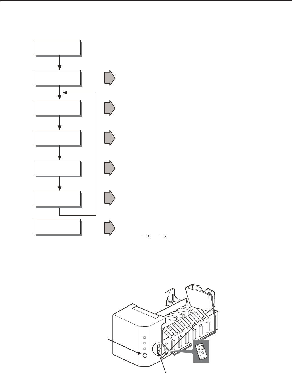
7-1 OPERATION PRINCIPLE
7-1-1 Operation Principle of Icemaker
7. OPERATION PRINCIPLE AND REPAIR METHOD OF ICEMAKER
1. Turning the Icemaker stop switch off (O) stops the icemaking function.
2. Setting the Icemaker switch to OFF and then turning it back on will reset the icemaker control.
Start Position
Icemaking
Mode
Harvest
Mode
Park Position
Fill
•
Test Mode
Waits until water becomes cold after starting the
Icemaking operation.
• Runs MOTOR to drop ice from the tray into the ICE BIN.
• Performs Icemaking Mode after supplying water by operating
the SOLENOID in ICE VALVE.
• To operate LINE and SERVICE, press and hold the Fill Key
for 3 seconds. The icemaking will run through 3 stages:
Harvest Fill Icemaking.
• With the detect lever, checks if the ICE BIN is full.
Power (On/Off) Switch
Water amount
control button
Power On
• Adjusts Ejector to Start Position whit power on.
- 22 -
Contents Summary of Kenmore 795 69292 902
- Page 1R TOP FREEZER REFRIGERATOR REFRIGERATOR SERVICE MANUAL CAUTION BEFORE SERVICING THE UNIT, READ THE SAFETY PRECAUTIONS IN THIS MANUAL. MODELS: 795.69292.902 795.79292.902 795.69293.902 795.79293.902 795.69299.902 795.79299.902 795.69372.902 795.79372.902 795.69374.902 795.79374.902 795.69376.902 795.
- Page 2CONTENTS WARNINGS AND SAFETY PRECAUTIONS .................................................................................... 2 1. SPECIFICATIONS ......................................................................................................................... 3 2. PARTS IDENTIFICATION ......
- Page 31. SPECIFICATIONS 1-1 DISCONNECT POWER CORD BEFORE SERVICING IMPORTANT RECONNECT ALL GROUNDING DEVICES. All parts of this appliance capable of conducting electrical current are grounded. If grounding wires, screws, straps, clips, nuts or washers used to complete a path to ground are removed for serv
- Page 41-7 REPLACEMENT PARTS PERFORMANCE DATA (NORMAL OPERATING CONDITIONS) SYSTEM PRESSURE (PSIG) Relay (PTC) ..................................EBG32606502 AMB WATTS Overload Protector (OLP) ............. 6750C-0005P HIGH SIDE LOW SIDE Defrost Thermostat ....................... 6615JB2005C 70°F 98 (+10 /
- Page 52. PARTS IDENTIFICATION A B J C D E K F L M G N H I O Use this section to become more familiar with the parts and features. Page references are included for your convenience. NOTE:This guide covers several different models.The refrigerator you have purchased may have some or all of the items listed
- Page 63. DISASSEMBLY 3-1 REMOVE FREEZER DOOR 3-2 REMOVE REFRIGERATOR DOOR • Loosen and remove the 2 bolts and the phillips head • Gently pry o the Top Hinge Cover with a at head screw to remove the Middle Hinge Bracket from screwdriver and remove (see Fig 1). refrigerator housing (Fig. 4 and 5). Set parts
- Page 73-3 REPLACE REFRIGERATOR DOOR • Set door onto Bottom Hinge Pin. • Place Upper Hinge’s Pin in the top of freezer door and line up the Upper Hinge with holes in top of • Place Hinge Pin of Middle Hinge Bracket inside refrigerator. Use the 3 bolts to replace Hinge (Fig. 10). Hinge Pin Insert on top of
- Page 83-5 REVERSE FREEZER DOOR • Gently pry off the Top Hinge Cover with a flat head • Move the Hinge Pin Insert Bracket to the other side screwdriver and remove (see Fig.13). of the door, keeping the same orientation, and move the Hinge Pin Insert into the hole on the left side of the bracket (Fig. 17).
- Page 93-6 REVERSE AND REATTACH REFRIGERATOR DOOR • Remove base grill. • Using a ¼-inch socket wrench, loosen and remove • Remove the washer from the Bottom Hinge Pin (Fig.22). Hinge Pin from the Middle Hinge Pin Bracket. Remove washer underneath the middle hinge and • Using a ¼-inch socket wrench, loosen
- Page 10• At this point, remove the Decorative Bolt on bottom on • Take out the Hinge Pin Insert and move the Bracket to the refrigerator housing from the left side of refrigerator other side of the door,keeping the same orientation (Fig. 28). (Fig. 24). You will need this hole for the Bottom Hinge. • Place
- Page 11• Following illustration, flip the Middle Hinge Bracket (Flange • Tighten bolts. Force-fit Top Hinge Cover over Top Hinge. will now be on top) and position on left side of refrigerator and re-attach with two bolts and a Phillips screw. (Fig. 32). • Place refrigerator door down over pin on bottom hin
- Page 123-7 LEVELING AND DOOR CLOSING 3-8 DOOR ALIGNMENT To avoid vibration, the unit must be leveled. If necessary, If the space between your doors is uneven, follow the adjust the Leveling Legs to compensate for unevenness instructions below to align the doors: of the floor. The front should be slightly h
- Page 133-9 FAN AND FAN MOTOR 3-11 LAMP 1. Remove the freezer shelf. (If your refrigerator has an icemaker, unplug and remove the icemaker first). 2. Remove the screw of the cover grille fan 3. Remove the grille by pulling it out and by loosening a screw. 4. Remove the Fan Motor assembly by loosening 4 scre
- Page 144. COMPRESSOR ELECTRICAL 4-2-4 Role of Combo TSD 4-1 COMPRESSOR 4-1-1 Role (1) The combo is attached to the sealed compressor and is used for the operation and protect the motor. The compressor intakes low temperature and low pressure gas (2) The compressor is a single phase induction motor. During
- Page 154-2-6 Motor Resarting and PTC/ Combo Cooling 4-3-2 Role of the OLP (1) It requires approximately 5 minutes for the pressure to (1) The OLP is attached to the sealed compressor used for the equalize before the compressor can restart. refrigerator. It prevents the motor coil from being started in the
- Page 165. CIRCUIT DIAGRAM PWB(PCB) ASSEMBLY, DISPLAY 2 1 3 4 5 6 RD BN PK YL BL PR CON101 RT-SENSOR A B RD BN PK YL BL PR WH WH GY GY 1 2 3 4 5 6 11 10 9 8 7 6 5 4 3 2 1 1 2 3 4 CON5 CON6 CON8 1 CON4 CON7 1 C-FAN SB 2 2 DEF-SENSOR BN 3 3 BO PR 4 4 BO F-FAN GY 5 PWB(PCB) ASSEMBLY, MAIN 5 WH WH 6 6 WH 7 7 R-
- Page 176. TROUBLESHOOTING 6-1 COMPRESSOR AND ELECTRIC COMPONENTS (Rated voltage YES Remove PTC-Starter/Combo 1 Power Source. from compressor and ±10%)? 2 measure voltage between Terminal C of compressor and terminal 5 or 6 of PTC/Combo YES No voltage. OLP disconnected? Replace OLP. 5 NO Check connection co
- Page 186-2 PTC / COMBO AND OLP Normal operation of Separate PTC-Starter/Combo Observation value is compressor is impossible from Compressor and 115V/60Hz : 6.8 ±30% PTC/ Combo OK or poor. measure resistance at room temperature between No. 5 and 6 of PTC-Starter with a Tester. (Figure 1 and figure 2) The re
- Page 196-3 OTHER ELECTRIC COMPONENTS • Not cooling at all Compressor Check for open short or Cause doesn't run. incorrect resistance readings in the following components a. Starting devices Short, open or broken. Poor contact b. OLP or shorted. c. Compressor coil Coil open or shorted. Poor contact Replace
- Page 206-4 SERVICE DIAGNOSIS CHART COMPLAINT SYMPTOM POSSIBLE CAUSES SOLUTION Electronic Display not 1. No Display at all operating correctly 1. Supply voltage not within specifications 1. Check supply voltage to refrigerator 2. Open in wiring harness from PWB board 2. Chack wiring and connectors to PWB bo
- Page 216-5 REFRIGERATING CYCLE • Troubleshooting Chart TEMPERATURE STATE OF STATE OF THE CAUSE OF THE REMARKS THE UNIT EVAPORATOR COMPRESSOR PARTIAL Freezer Low flowing sound of A little higher • Refrigerant level is low due LEAKAGE compartment and Refrigerant is heard and than ambient to a leak. Refrigera
- Page 227. OPERATION PRINCIPLE AND REPAIR METHOD OF ICEMAKER 7-1 OPERATION PRINCIPLE 7-1-1 Operation Principle of Icemaker Power On Start Position • Adjusts Ejector to Start Position whit power on. Icemaking • Waits until water becomes cold after starting the Mode Icemaking operation. Harvest Mode • Runs MO
- Page 237-2 ICEMAKER FUNCTIONS 7-2-1 Start Position 1. After POWER OFF or Power Outage, check the EJECTOR's position with MICOM initialization to restart. 2. How to check if it is in place: - Check HIGH/LOW signals from HALL SENSOR in MICOM PIN. 3. Control Method to check if it is in place: (1) EJECTOR is i
- Page 247-2-4 Fill/Park Position 1. Once a normal harvest mode has been completed, the water solenoid will be activated. 2. The amount of water is adjusted by pressing the Fill Key repeatedly. This changes the time allowed for fill as illustrated in the table below. Water supply amount TABLE STAGE TIME TO S
- Page 257-2-5 Function TEST 1. This is a compulsory operation for test, service, cleaning, etc. It is operated by pressing and holding the fill key for 3 seconds. 2. The test works only in the Icemaking Mode. It cannot be entered from the Harvest or Fill mode. (If there is an ERROR, it can only be checked i
- Page 268. DESCRIPTION OF FUNCTION & CIRCUIT OF MICOM 8-1 FUNCTION 8-1-1 Function 1. When the appliance is plugged in, is set to “3” for the refrigerator. You can adjust the Refrigerator control temperature by pressing the ADJUST button. 2. When the power is initially applied or restored after a power failu
- Page 278-1-4 Defect Diagnosis Function 1. If there is a problem, an error code will appear.. 2. The buttons will not operate. 3. When the problem is repaired, the display will return to normal. 4. The error code is displayed using the LEDs. 1 2 3 4 5 WARMER COLDER TEMPERATURE ADJUST • ERROR CODE on Refrige
- Page 288-1-5 TEST MODE 1. Test mode allows checking the PCB and the function of the product as well as determining the Defective part in case of an error. 2. The test button is on the main PCB of the refrigerator (Test S/W). 3 While in the test mode, the ADJUST button will not operate. 4. After exiting the
- Page 298-2 PCB FUNCTION Con 2 Con 3 Con 1 Con 8 Con 2 Con 5 Con 6 Con 7 - 29 -�
- Page 308-2-1 Power Circuit Power is supplied to the control board at the pin 11 and 9 of connector #1. (Refer to figure 1) CON3 CON1 CON2 3 2 1 11 10 9 8 7 6 5 4 3 2 1 1 2 3 4 5 6 7 SB BN YL BL BL BK SB BN POWER SB BN YL BL BL BK SB BN SUPPLY CORD DOOR S/W-R N FUSE-M L com com (72 C) GN/YL (GN) CAPACITOR P
- Page 312. Door Monitor Circuit (LV) Measurement between Refrigerator CONNECTOR 8 pins 4 and 3 Con 8 Door Close 0 volts PIN 1 2 3 4 Door Open 5 volts RT-SNR R-DOOR S/W 8-2-3 Temperature Sensor Circuit (Refer to figure 2) Voltage supplied to each sensor wil range between 0.5 volts -22°F(-30°C) and 4.5 volts
- Page 328-3 RESISTANCE SPECIFICATION OF SENSOR RESISTANCE OF REFRIGERATOR & TEMPERATURE DEFROST SENSOR VOLTAGE -20 °C (-4 °F) 77 3.73 -15 °C (5 °F) 60 3.49 -10 °C (14 °F) 47.3 3.22 -5 °C (23 °F) 38.4 2.95 0 °C (32 °F) 30 2.67 5 °C (41 °F) 24.1 2.4 10 °C (50 °F) 19.5 2.14 15 °C (59 °F) 15.9 1.89 20 °C (68 °F
- Page 33#EV# 9. EXPLODED VIEW (Better IM Ready Models) CASE PARTS CAUTION: Use the part number to order part, not the position number . 103B 301A 401A 281A B01 281B S01 103A 501F 282E 418A 410G 411A 623H 282B 282X 406B 120A 501A 145A 304A S01 282H S01 S14 120B 903D 503C 503D S16 105A 125D 409B 619B S01 317A
- Page 34#EV# FREEZER PARTS CAUTION: Use the part number to order part, not the position number . 405F 330B 332A S01 110D 405C 319E 284A S22 404A 329A 284C 125A 131A 149F 404Z 149A -34-�
- Page 35#EV# REFRIGERATOR PARTS CAUTION: Use the part number to order part, not the position number . 143E 140D S24 140B 140E 143F 142D S24 140B 142E S24 S24 128A 170A 128B 143E 140D S24 140B 140E 143E 140D S24 140B S24 140E S24 103E 167B 154A 103E 151A 155B 151A 151C -35-�
- Page 36#EV# DOOR PARTS CAUTION: Use the part number to order part, not the position number 200A 201A 205D 203A 212G 205D 286A 210B 210A 241A 230A 233A 231A 241B 241C 281E 241E 241C 241C 286A 241D 243A 283F -36-�
- Page 37