Kenmore 795 71303 902 Page 22
Workshop Manuals
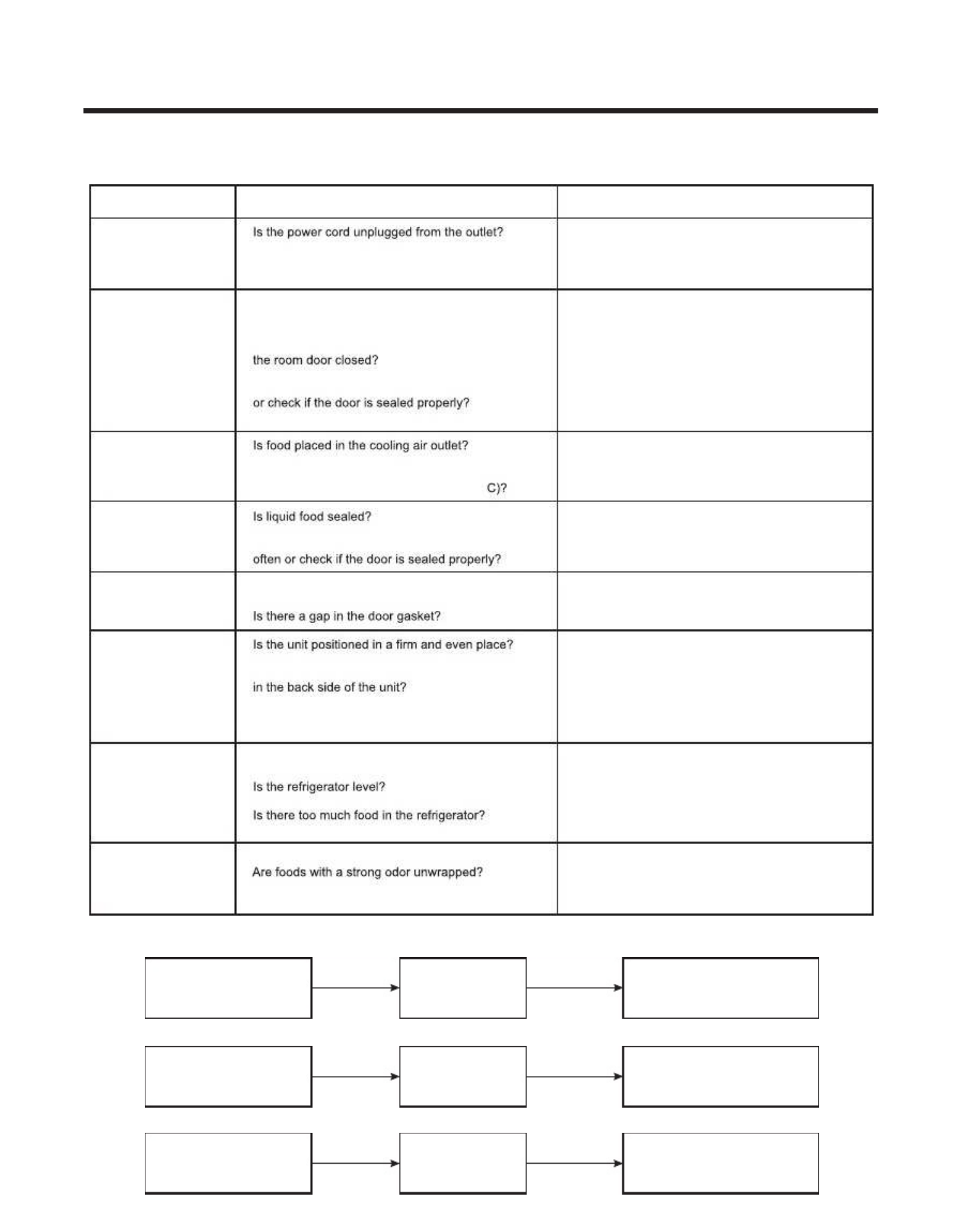
6-4 SERVICE DIAGNOSIS CHART6-4 SERVICE DIAGNOSIS CHART
CC
OO
MM
PP
LL
AA
II
NN
TT
PP
OO
II
NN
TT
S S
TT
O O
BB
E E
CC
HH
EE
CC
KK
EE
DD
RR
EE
MM
EE
DD
YY
• Other possible problems:• Other possible problems:
Check if frost forms inCheck if frost forms in
the freezer.the freezer.
Check ComponentsCheck Components
of the defrostingof the defrosting
circuit.circuit.
Check theCheck the
refrigeration system.refrigeration system.
Check theCheck the
Thermistor.Thermistor.
NotNot
defrostingdefrosting
The systemThe system
is fis f
aultyaulty
..
Perform sealedPerform sealed
system repair.system repair.
Replace theReplace the
Thermistor.Thermistor.
The operation ofThe operation of
the Thermistor isthe Thermistor is
incorrect.incorrect.
No Cooling.No Cooling.
Cools poorly.Cools poorly.
Foods in theFoods in the
RefrigeratorRefrigerator
are frozen.are frozen.
Condensartion or iceCondensartion or ice
forms insideforms inside
the unit.the unit.
Condensartion formsCondensartion forms
in the Exterior Case.in the Exterior Case.
There is abnormalThere is abnormal
noise.noise.
Door does notDoor does not
close well.close well.
Ice and foodsIce and foods
smell unpleasant.smell unpleasant.
••
• Check if t• Check if t
he power swihe power swi
tch is set ttch is set t
o OFFo OFF
..
• Check if the fuse of • Check if the fuse of
the power switch is shorted.the power switch is shorted.
• Measure the voltage of the power outlet• Measure the voltage of the power outlet
..
• Check if the unit is • Check if the unit is
placed too close to the wall.placed too close to the wall.
• Check if the unit is • Check if the unit is
placed too close to the stove,placed too close to the stove,
gas cookergas cooker
, or in , or in
direct sunlight.direct sunlight.
• Is the ambient temperature too • Is the ambient temperature too
high orhigh or
• Check if food put in • Check if food put in
the refrigerator is hot.the refrigerator is hot.
• Did you open the door of the unit too often• Did you open the door of the unit too often
• Check if the Control is set • Check if the Control is set
toto
Warm positionWarm position
..
••
• Check if the control is set • Check if the control is set
toto
colder positioncolder position
..
• Is the ambient temperature below 41°F(5°• Is the ambient temperature below 41°F(5°
••
• Check if food put in • Check if food put in
the refrigerator is hot.the refrigerator is hot.
• Did you open the door of the unit too• Did you open the door of the unit too
• Check if the ambient temperature and • Check if the ambient temperature and
humidityhumidity
of the surrounding air are high.of the surrounding air are high.
••
••
• Are any unnecessary objects placed• Are any unnecessary objects placed
• Check if the Tray Drip is not firmly fixed.• Check if the Tray Drip is not firmly fixed.
• Check if the cover of the • Check if the cover of the
compressor enclosurecompressor enclosure
in the front lower side is tin the front lower side is t
aken out.aken out.
• Check if the door gasket is dirty • Check if the door gasket is dirty
withwith
an item like juice.an item like juice.
••
••
• Check if the inside of • Check if the inside of
the unit is dirtythe unit is dirty
..
••
• The unit smells of plastic.• The unit smells of plastic.
• Plug into the outlet.• Plug into the outlet.
• Set the switch to ON.• Set the switch to ON.
• Replace the fuse.• Replace the fuse.
• If the voltage is • If the voltage is
lowlow
, correct the wiring., correct the wiring.
• Place the unit about 4 inches (10 cm) from the wall.• Place the unit about 4 inches (10 cm) from the wall.
• Place the unit away from • Place the unit away from
these heat sources.these heat sources.
• Lower the ambient temperature.• Lower the ambient temperature.
• Put in foods after • Put in foods after
they have cooled down.they have cooled down.
• Don't open the door too oft• Don't open the door too oft
en and closeen and close
it firmly.it firmly.
• Set the control to• Set the control to
Recommended positionRecommended position
..
• Place foods in the high-temperature section.• Place foods in the high-temperature section.
(front part)(front part)
• Set the control to• Set the control to
Recommended positionRecommended position
..
• Set the control to• Set the control to
Warm positionWarm position
..
• Seal liquid foods with wrap.• Seal liquid foods with wrap.
• Put in foods after • Put in foods after
they have cooled down.they have cooled down.
• Don't open the door too oft• Don't open the door too oft
en and closeen and close
it firmly.it firmly.
• Wipe moisture with a dry cloth. • Wipe moisture with a dry cloth.
It will disappearIt will disappear
in low in low
temperature and humidity.temperature and humidity.
• Fill up the gap.• Fill up the gap.
• Adjust the Leveling Screw, and position the• Adjust the Leveling Screw, and position the
refrigerator in a firm place.refrigerator in a firm place.
• Remove the objects.• Remove the objects.
• Fix the Tray Drip firmly in the original position.• Fix the Tray Drip firmly in the original position.
• Place the cover in its original position.• Place the cover in its original position.
• Clean the door gasket.• Clean the door gasket.
• Position in the firm place and level the• Position in the firm place and level the
Leveling Screw.Leveling Screw.
• Make sure food stored in shelves does not prevent• Make sure food stored in shelves does not prevent
the door from closing.the door from closing.
• Clean the inside of the unit.• Clean the inside of the unit.
• Wrap foods that have a strong odor.• Wrap foods that have a strong odor.
• New products smell of plastic, but this• New products smell of plastic, but this
will go away after 1-2 weeks.will go away after 1-2 weeks.
- 20 -- 20 -
Contents Summary of Kenmore 795 71303 902
- Page 1BOTTO BOT TOMM FRE FREEZE EZER R REF REFRIG RIGERA ERATO TOR R REFRIGERATOR SERVICE MANUAL CAUTION BEFORE SERVICING THE PRODUCT READ THE SAFETY PRECAUTIONS IN THIS MANUAL. MODELS: 795.71303.902 795.71306.902 795.71302.902 795.71309.902 795.71304.902 MFL62078232 Sears Brands Management Management Cor
- Page 2ECN (Engineering Change Number) Rev.01 Valve inclined in order to improve house connection Rev.02 Compressor change from MQ53LAUM (PTC) to MQ53LAUM (e-PTC)
- Page 3CONTENTS SAFETY PRECAUTIONS ............. ........................... ............................. ............................. ............................. ............................. ............................ ................... ..... 3 1. SPECIFICATIONS ............. .....................
- Page 4SAFETY PRECAUTIONS Please read the following instructions before servicing your refrigerator refrigerator.. 1. Check the refrigerator for current leakage. 7. Before tilting the refrigerator refrigerator,, remove all materials from on or in the refrigerator. 2. To To prevent electric e lectric shock,
- Page 51. SPECIFICATIONS 1-1. DISCONNECT POWER CORD BEFORE SERVICING IMPORTANT: Reconnect all grounding devices. All parts of this appliance appliance capable of conducting electrical electrical current are grounded. If grounding wires, screws, straps, clips, nuts or washers used to complete a path to grou
- Page 61-7. REPLACEMENT PARTS PERFORMA NCE DATA PERFORMANCE (NORMAL OPERATING CONDITIONS) Relay........................................................... EBG42993601 Overload.................... Overload......... ...................... ..................... ..................... ............. 6750C-0005P
- Page 7DIMENSIONS Description 7130* Depth w/ Handles A 34 5 8 1 Depth w/o Handles B 32 8 Depth w/o Door C 28 ¼ Depth (Total with Door Open) D 45 ½ Height to Top of Case E 67 11 16 Height to Top of Door Hinge F 69 1 16 Width G 32 ¾ Width (door open 90 deg. w/o handle) H 36 ¼ Width (door open 90 deg. w/ hand
- Page 82. PARTS IDENTIFICATION A B K C L D E F M G N H O I J Use this section to become more familiar with the parts and features. NOTE: This guide covers several different models. The refrigerator you have purchased may have some or all of the items listed below. The locations of the features shown below
- Page 93. DISASSEMBLY 3-1 FAN AND FAN MOTOR 3-3 LAMP 1. Remove the freezer shelf. (If your refrigerator has an icemaker, remove the icemaker first). 2. Remove the plastic guide for slides on left side by unscrewing phillips head screws. 3. Remove the grille by removing one screw and pulling the grille forw
- Page 103-4 CONTROL CON TROL BOX-REFRIGERA BOX-REFR IGERATOR TOR 1. First, remove all shelves in the refrigerator, than remove the Refrigerator control Box by loosening 2 screws. CONTROL BOX COVER LAMP Fig. 6 2. Remove the Refrigerator Control Box by pulling it downward. 3. Disconnect the lead wire on the r
- Page 113-6 DOOR DISASSEMBLY 3-6-1 REMOVE REFRIGERATOR DOOR 3-6-2 REPLACE REFRIGERATOR DOOR IMPORTANT: Before you begin, turn the refrigerator OFF and IMPORTANT: Before Right Door Unplug it. Remove food and any bins from doors. Lower the door onto the middle hinge pin (7). Left Door Make sure the door is al
- Page 123-6-3 PULL OUT DRAWER (a) HOW TO REMOVE PULL OUT DRAWER IMPORTANT: To avoid possible injury, product or CAUTION: When removing drawer door, do not hold it property damage, you will need two people to perform by the handle. Door could fall down and you may be the following instructions. injured grasp
- Page 13(b) HOW TO INSTALL PULL OUT DRAWER IMPORTANT: To avoid possible injury, product or • Align the top holes of the rail cover with the top holes of property damage, you will need two people to perform the door supports to assemble the r ail cover. the following instructions. • With both hands, hold the
- Page 143-6-4 HOW TO REMOVE DOOR HANDLES NOTE: Handle appearance may vary from illustrations 2. Removi Removing ng Freezer Drawer Handle on this page. • Loosen the set screws located on the lower side of the handle with the 3/32” Allen 1. Removi Removing ng Refrigerator Refrigerator Handle wrench and remove
- Page 153-7 LEVELING AND DOOR ALIGNMENT (a) LEVELING (b) DOOR ALIGNMENT Your refrigerator has two front leveling screws one on If the space between your doors is uneven, follow the the right and one on the left. If your refrigerator seems instructions below to align the doors: unsteady or you want the doors
- Page 164. ADJUSTMENT 4-1 COMPRESSOR 4-2-3 PTC-Applied Circuit Diagram Starting Method for the Motor 4-1-1 Role The compressor intakes low temperature and low pressure gas from the evaporator of the refrigerator and compresses OVERLOAD PROTECTOR this gas to high-temperature and high-pressure gas. It then L1
- Page 174-3 OLP (OVERLOAD PROTECTOR) 4-3-1 Definition of OLP (1) OLP (OVERLOAD PROTECTOR) is attached to the Compressor and protects the Motor by opening the circuit to the Motor if the temperature rises and activating activat ing the bimetal bimet al spring in the OLP OL P. (2) When high current flows to t
- Page 185. CIRCUIT DIAGRAM - 16 -
- Page 196. TROUBLESHOOTING 6-1. COMPRESSOR AND ELECTRIC COMPONENTS (Rated voltage YES Remove PTC-Starter 1 Power Source. from compressor and 2 measure voltage between Termina Terminall C of compressor and terminal 5 or 6 of PTC. YES No voltage. Reconnect. 5 NO Check connection condition. Replace OLP. Applie
- Page 206-2. PTC AND OLP Normal operation of Separate PTC-Starter Observation value is compressor is impossible from Compressor and 115V/60Hz : 6.8 ? ±20% or poor. measure resistance between No. 5 and 6 of PTC-Starter with a Tester. (Figure 1) The resistance value Replace PTC- is 0 ? (short) or Starter. (op
- Page 216-3 OTHER ELECTRICAL COMPONENTS • Not cooling at all Compressor Check for open short or doesn't run. Cause incorrect resistance readings in the following components a. Starting devices Short, open, or broken. Poor contact b. OLP or shorted. c. Compressor coil Coil open or shorted. d. Wirin Wiringg h
- Page 226-4 SERVICE DIAGNOSIS CHART COMPLAINT POINTS TO BE CHECKED REMEDY No Cooling. • • Plug into the outlet. • Check if the t he power switch swi tch is set to t o OFF. OFF. • Set the switch to ON. • Check if the fuse of the power switch is shorted. • Replace the fuse. • Measure the voltage of the power
- Page 236-5 REFRIGERATION CYCLE • Troubleshooting Chart - 21 -
- Page 246-5-1 SEALED SYSTEM DIAGNOSIS Not Cooling Complaint All components operating, No airflow problems, Not frosted up as a defrost problem problem has been isolated to sealed system area Frost Partial None Pattern? Equalization Equalization Test Test Very Fast Fa st Very Slow Very Slow Fast Very Fast F
- Page 257. OPERATION PRINCIPLE AND REPAIR METHOD OF ICEMAKER 7-1 OPERATION OPERATION PRINCIPLE PRI NCIPLE 7-1-1 Operation Principle of Icemaker Power Input Initial Control • Adjusts Ejector to Start Position with Position with power on. Icemaking Control • Waits until water in the TRAY is frozen after Icema
- Page 267-2 ICEMAKER FUNCTIONS 7-2-1 Start Position 1) When power is initially applied or reapplied after power is cut, it detects level of the TRAY after completion of MICOM initialization. The detecting lever moves up and down. 2) The level of icemaker tray is judged by output signal, high and low signal,
- Page 27MAXIMUM TILTING POINT Bank is not full ON HALL Sensor OFF Output Signals Bank is full ON HALL Sensor Output Signals OFF Ice checking AXIS LEVEL 30° Ice checking AXIS -0° -10° -8°-0° -8° -32° -41° -53° -58° -80° -160° -170° Lock Lock Icemaking Ice ejection original point A B C 2±1 sec Horizontal 9±3
- Page 287-2-4 Test Icemaker Mode Test function starts when test switch is press ed for more than 3 seconds. seconds. User shouldn’t force operation while doing test mode, service or cleaning. Test switch will work only when ice tray its in horizontal position, not during ice ejection or water supplying. Whe
- Page 298. CIRCUIT OF MICOM 8-1 FUNCTION 8-1-1 Function 1. Initially set the Refrigerator control at 37ºF (3ºC) and the Freezer control at 0ºF(-18ºC) You can adjust the Refrigerator and the Freezer control temperature by pressing the Colder ADJUST button. 2. When the power is restored after a power failure,
- Page 308-1-6 Alarm for Open Door 1. This feature sounds a buzzer when the freezer or refrigerator door is not closed within 1 minute after it is opened. 2. One minute after the door is opened, the buzzer sounds three times each for 1/2 sec onds. These tones repeat every 30 seconds. 3. The alarm is cancelle
- Page 318-1-10 Defect Diagnosis Function Micom error are separated in “Main Errors” (Affect directly refrigerator performance) and “Secondary Errors” (don’t affect the refrigerator performance). To check in Display the error present, is necessary press Cold key on freezer and Cold key on refrigerator more t
- Page 328-1-11 TEST Mode 1. The Test mode allows checking the PCB and the function of the product as well as finding out the defective part in case of an error. 2. The test mode is operated by pressing two buttons on the Display panel. 3. While in the test mode, the function control button is not recognized
- Page 338-2 PCB FUNCTION CON 7 CON 6 CON 5 CON 4 CON 8 CON 9 CON 10 CON 1 CON 3 CON 2 - 31 -
- Page 348-2-1 Power Circuit Fig. 1 8-2-2. Load and Door Light Circuit (HV) 1. Load Drive Condition Check To measure outputs of the control board, check voltages between the pins for the following components: (Refer to Fig. 1). Pin Pin Output Circuit Number Number Voltage Connector 1 Compressor Con 1 Pin 1 C
- Page 35Fig. 2 2. Door Monitor Circuit Ci rcuit (LV) Refrigerator Pin Number Pin Number Voltage F Door Close Con 7 Pin 4 Con 7 Pin 5 5 Volts F Door Open Con 7 Pin 4 Con 7 Pin 5 0 Volts R Door Close Con 8 Pin 3 Con 8 Pin 4 5 Volts R Door Open Con 8 Pin 3 Con 8 Pin 4 0 Volts Connector 8 Pin 4 3 2 1 R-Door S/W
- Page 36To measure the outputs of the sensors, check the voltages between the pins as in the table. And refer the values in the section “RESISTANCE SPECIFICATION SPECIFICATION OF SENSOR” Sensor Pin Number Pin Number F- Sensor Con 7 Pin 10 Con 7 Pin 11 R- Sensor Con 7 Pin 8 Con 7 Pin 9 D- Sensor Con 7 Pin 6
- Page 378-3 RESISTANCE SPECIFICATION OF SENSOR TEMPERA TEMPE RATURE TURE DETECTE DETECTED D RESISTANCE OF FREEZER RESISTANCE OF REFRIGERATOR SENSOR SENSOR DEFROST SENSOR & ROOM SENSOR -20°C 22.3 K? 77 K? -15°C 16.9 K? 60 K? -10°C 13.0 K? 47.3 K? -5°C 10.1 K? 38.4 K? 0°C 7.8 K? 30 K? +5°C 6.2 K? 24.1 K? +10°
- Page 38
- Page 39#EV# FREEZER PARTS CAUTION: Use the part number to order part, not the position number. number. 136B 131A 145C 248E 248F 145F 136A
- Page 40#EV# REFRIGERATOR PARTS CAUTION: Use the part number to order part, not the position number. number. 147C 147A 143F 141B 143F 141B 141C 248G 141C 248G 143F 141B 143F 141B 141C 248G 141C 248G
- Page 41#EV# REFRIGERA REFRIGE RATOR TOR PARTS (P (PANTRY) ANTRY) Caution: Use the part number to order part, not the position number. 167B 154A 145J 151B 145G 151A 145H 154B 128B 170A 128A
- Page 42#EV# DOOR PARTS CAUTION: Use the part number to order part, not the position number. number. 230B 230A 104E 233D 233A 231A 231B 233B 233C 241F 212G 241A 248L 241C 241B 233G 233H 248M 212K 241C 212K 241H 248L 248M 248L 241C 244A 241H 233F 244A 212J 233E 212J 248M 241H 241C 248M 248L 241C 248L 212K 28
- Page 43#EV# WATER & ICEMAKER IC EMAKER PARTS Caution: Use the part number to order part, not the position number. 600A 622B 627A 616E 619C S31
- Page 44