Samsung Refrigerator Technology Page 25
Workshop Manuals
Error Code Display Pt 6
Error items for self-diagnosticsError items for self-diagnostics
TROUBLETROUBLELEDLED
Error itemsError items
NONO
CodesCodes
areare
21
CF Compartment fan motor stuck or spinning to fastCF Compartment fan motor stuck or spinning to fast
CF-FAN ERRORCF-FAN ERROR
shownshown
forfor
example,example,
a full lista full list
CR Compartment fan motor stuck or spinning to CR Compartment fan motor stuck or spinning to fastfast
CR-FAN ERRORCR-FAN ERROR
22
o o ccooeess
for thefor the
specificspecific
productproduct
isis
Ice Maker Fill line heater measures openIce Maker Fill line heater measures open
ICE PIPE HEATERICE PIPE HEATER
24
availableavailable
in thein the
serviceservice
manualmanual
41
Contents Summary of Samsung Refrigerator Technology
- Page 1Chapter 2 Refrigerator Technology 17�
- Page 2Dual Evaporator with TDM valve The Time Divided Multi‐cycle (TDM) System (Stepper Valve) is used to switch refrigerant flow nt e oor an renc oor . This improves temperature control and energy efficiency. Quad Cooling RM Model Twin Cooling RS/RF/RB Models 18
- Page 3Inverter Compressor standard compressor 19�
- Page 4Refrigerant Path Compressor Sub-condenser Hot Pipe Dryer Step valve R Capillary Tube R/CR Evaporator C Capillary Tube F Capillary Tube C/CF Evaporator Suction Pipe Compressor 20�
- Page 5Chapter 3 Refrigerator Troubleshooting 21�
- Page 6Refrigeration Troubleshooting • The Forced Operation Mode is a very valuable troubleshooting tool for testing compressor operation, fan opera on an e ros o pera on. • Forced Freeze Mode • • You can check the compressor voltage at the main PCB in this mode. • ou can accura e y c ec e ros sensor vo ag
- Page 7Refrigeration Troubleshooting • The compressor is started without the 5 minute delay • compressor • You can accurately check the temp and sensor operat on • All fans will be turned on in this mode, to allow voltage . . 23
- Page 8Refrigeration Troubleshooting • Forced Defrost Operation • Standard compressor models can activate the Fridge defrost only, or both the Fridge and Freezer defrost. • Inverter compressor models activate all heaters at once. controls the heater operation. When defrost is activated the main PCB will tu
- Page 9Refrigeration Troubleshooting • Selecting the Forced Modes • When the two buttons are pressed together to enter the Forced Modes you must wait for the beep and the display to go blank. You then have 8 seconds to press e reeze u on oa c vae e orce reeze Mode. Once you are in this mode, press the Free
- Page 10Forced Operation and Test Mode FF ForcedCompressorRun Test Mode RD Forced Refrigerator Defrost Press both buttons simultaneously for 8 seconds! FD ForcedFreezerDefrost -- TestModeactive Press any button one more time to cancellation Forced Mode Cancellation Forced De fro st orce e ros Operation for
- Page 11Forced Operation For va rio us refri gera tor p anels Cancellation, unplug unit Wait 5 seconds between Press Freezer button a button pushes third time to Force Press Freezer button One time at the Press Freezer button Second Defrost for Fridge & Test Mode to Force Compressor time for Forced Defrost
- Page 12RFG29* Series Inverter Compressor Forced Mode For Test Mode Press both buttons simultaneously for ~15 seconds! Press Freezer button One time at the Test Mode to Force each Compressor test Forced Forced Forced Wait 5 seconds between ompressor ompressor ompressor button presses High Mid Low 3600 RPM 2
- Page 13RM257*** Series Inverter Compressor Forced Mode For Test Mode Press both buttons simultaneously for ~15 seconds! Press Freezer button One time at the Test Mode to Force each Compressor test Forced Forced Forced Wait 5 seconds between button presses High Low Mid ~ 3600 RPM ~ 2450 RPM ~ 2050 RPM Simul
- Page 14Forced Mode for Single Evaporator units Use Freezer Key as a Test Key Wait 5 seconds between RS26/2530** 30�
- Page 15Refrigeration Troubleshooting • The Diagnostic Mode is the most valuable troubleshooting tool you have for troubleshooting a refrigerator. When you are at e p r ou c s s e rs e s y o u so u o. • When a Samsung refrigerator is powered up if performs a Self Diagnosis, if an open or shorted sensor is d
- Page 16Refrigeration Troubleshooting • To enter the manual Diagnostic Mode you must press and hold two buttons, and hold them until the display stops blinking and beeps. • au co e sp ay or a mo e s a ave empera ure num ers n the display: – Each 8 is made up of 7 segments, each of those segments is a possib
- Page 17Refrigeration Troubleshooting • A Sample fault code would be this is an example of an Ice Maker Sensor failure. . • After a power failure the unit would be “dead”, lights work and blinking this code. • The Ice Maker is not making any ice • The Ice Maker is dumping partially frozen cubes • If you see
- Page 18Self Diagnostics r e ss o t uttons s mu taneous y or s eco n s If a corresponding LED flickers, it means an a norma y o a sensor or componen . 34�
- Page 19Self Diagnosis Hold Buttons until display stops blinking and beeps, then release and read fault codes.. Various refri erator anels are shown 35�
- Page 20Error Code Display Pt 1 Error items for self-dia nostics NO Error items LED TROUBLE 1 I/M-SENSOR Ice maker sensor measures o en or shorted Codes shown are for example, 2 R-SENSOR of codes Refrigerator sensor measures open or shorted for the specific product is av a a e DEFROSTING in the 3 SENSOR OF
- Page 21Error Code Display Pt 2 - NO Error items LED TROUBLE I/M FUNCTION Ice maker did not return to level after an ice harvest, this is Codes shown are for 5 ERROR displayed after three attempts example, of codes for the Refrigerator Compart ment defrosti ng heater- electric wire cut, R-DEFROSTING short-c
- Page 22Error Code Display Pt 3 Error items for self-dia nostics NO Error items LED TROUBLE DEFROSTING - 9 SENSOR OF CR wire cut, short-circuit, contact failure, or missing sensor. This can Codes shown are for COMPARTMENT also be caused by a temperature reading > 122 or < -58 . example, of codes DEFROSTING
- Page 23Error Code Display Pt 4 Error items for self-dia nostics NO Error items LED TROUBLE Codes are WATER HEATER a er eservo r ea er measures open shown ERROR for example, a full list o co es m en empera ure ensor rea s open or s or e 14 EXT-SENSOR for the specific product is available in the Freezer Temp
- Page 24Error Code Display Pt 5 Error items for self-diagnostics NO Error items LED TROUBLE Codes are Freezer fan motor stuck or spinning to fast - shown for example, a full list o co es ompressor an mo or s uc or sp nn ng o as 18 C-FAN ERROR for the specific product is available 19 CF-SENSOR CF Compartment
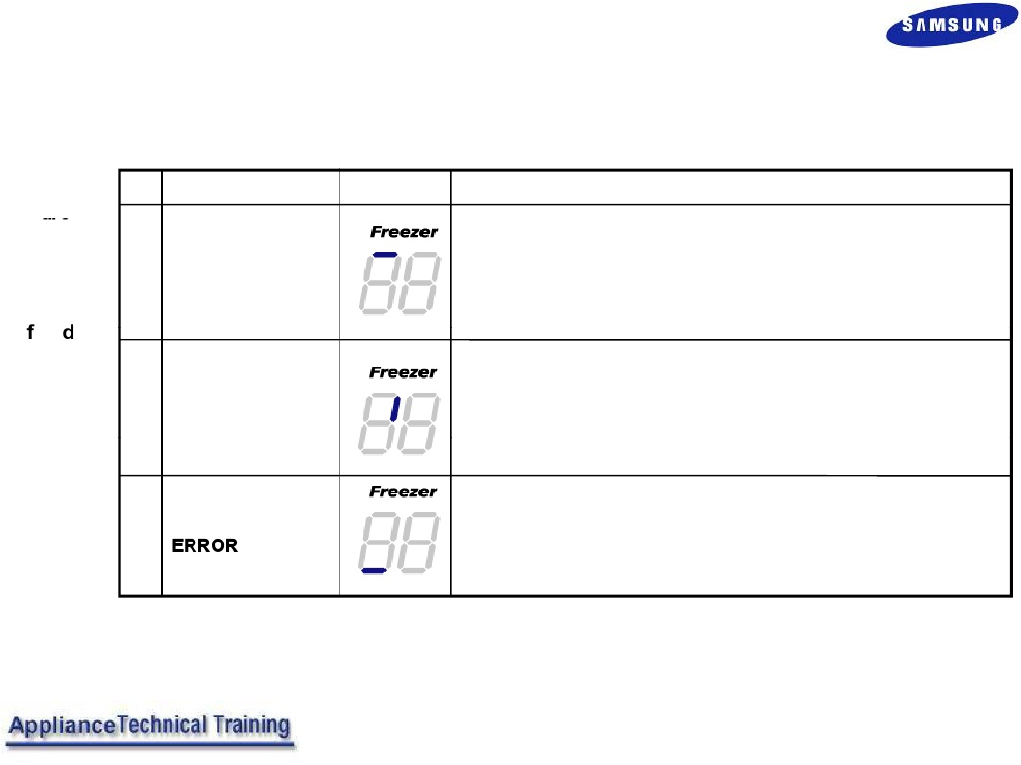
- Page 25Error Code Display Pt 6 Error items for self-diagnostics Codes NO Error items LED TROUBLE are shown for 21 CF-FAN ERROR CF Compartment fan motor stuck or spinning to fast example, a full list o co es for the specific product CR Compartment fan motor stuck or spinning to fast 22 CR-FAN ERROR is avail
- Page 26Error Code Display Pt 7 Error items for self-diagnostics Codes are shown NO Error items LED TROUBLE for Uart This error is not applicable if you encounter this error during example, diagnostics ignore it 25 COMMUNICATION a full list ERROR o co es for the L↔M specific COMMUNICATION product 26 ERROR B
- Page 272008 French Door Refrigerator Error Codes Codes are shown for example, a full list o co es for the specific product is available in the service manual 43�
- Page 282008 French Door Refrigerator Error Codes Codes are shown for example, a full list o co es for the specific product is available in the service manual 44�
- Page 29Defrosting Troubleshooting Check for any fault codes in the manual Diagnostic Mode ec or rozen ra n Ask the Consumer if there has been water or ice build up and/or open drain heater on the bottom of the Fridge compartment or the floor. NO YES Frozen Evaporator Replace heating element Is the Defrost
- Page 30Testing Defrost Circuits ccess e ma n or vo age res s ance es ng – With the compressor running test the sensors – Enter Forced Mode Defrost – Measure the heater voltage – Remove the power and heater connector and check the • Defrost Sensor – The sensor shuts off heater At 50℉ in Freezer, 63℉ in Frid
- Page 31Defrosting Troubleshooting Part 1 • – Testing : Check the DC voltage across both evaporator defrost sensors, with the compressor running. They should read less than a tenth of a volt difference, as they . ~ 3.7VDC, about after the 10 minutes. Youcompressor may find one hasreading been about running
- Page 32Defrosting Troubleshooting Part 2 Enter the Forced Mode per instructions • Check heater circuit amperage at the Main PCB or A/C line; ~. ~. 3.4 NOTE:amps total. If compartment is warm, you only have about 90 seconds . • Freezer - Check service manual for connector and wire color code for the model b
- Page 33Defrosting Troubleshooting Part 3 Enter the Forced Mode per instructions • 120VAC NOTE: If for Freezer and compartment is Fridge. warm, you only have about 90 seconds to . Listen for the relay closing then check the heaters. • - wire color code for the model being serviced. • Fridge Defrost Heater -
- Page 34Defrosting Troubleshooting Part 4 Heater circuit resistance - Unplug the refrigerator. Remove the defrost heater connector from PCB. • Freezer - Check heater circuit resistance at the Main PCB, look for 35–50 Ω average. • Fridge - Check heater circuit resistance at the Main PCB, look for 60-95 Ω ave
- Page 35Defrosting Troubleshooting Example of a 2600 Ω heater 51
- Page 36Defrost Error Symptoms NOTE: Evaporator covers may break if removed wh ile frozen as they are plastic, replace if damaged. • Ice build up in either the freezer or refrigerator compartment . is not being defrosted by the heaters enough to properly clear the drain and pass the melted water into the ca
- Page 37Defrosting Error Causes • The heat from the defrost heater does not transfer to the evapora or ra n • The Styrofoam around the evaporator cover absorbs moisture and frost begins to form on the evaporator, defective evaporator cover. • During the defrost cycle, the frost melts and drips down to the d
- Page 38Defrost Circuit Modification • “ ” “ ” evaporator. Thetometal defrost heaters clipspreventing the drain will touch and transfer ice build up. heat more efficiently from the Part numbers for these parts are as follows: - - , C: DA61-03585A FIXER-EVAP REF 54
- Page 39Compressor Controller board connector arran ement and detail ex lanation RM257AB* ① 12VDC ② 5VDC ③ Ground Forced Modes: ④ Compressor RPM FF1 - Compressor high speed - 2.7 amps FF2 - Compressor low speed - 1.6 amps FF3 - Compressor medium speed - 2.0 amps - -~. NOTE: FF2 & FF3 could be reversed. Chec
- Page 40Model: RFG294 **, RFG295**, RFG299** Com ressor Troubleshootin CN04 VDD VSS RPM FB CN01 POWER(115VAC) CN03 U V W CN02 OLP Compressor not running Check for 5 minute delay -- Not in delay Force Operation FF1 FF2 -- Compressor high speed Compressor medium speed -- 2.7 amps 2.0 amps If no operation, dis
- Page 41Diagnosing the Inverter Compressor The LED on the Inverter drive PCB will be off when the compressor is off and on whenever the compressor is running. If a defect should occur in the compressor the number of times the LED blinks will indicate where the fault might be. 57�
- Page 42Chapter 4 Common Refrigerator Service Issues 58�
- Page 43No Ice - Flex Tray I/M • or e cem a er oo pera ep roper y,w a erp ressure e ween an s required. A quick test of water pressure would be filling a 6 Oz paper cup in less than 10 seconds. If the internal water filter is clogged, the water pressure to the icemaker will be reduced. The foreign matter at
- Page 44Slow Ice - Flex Tray I/M • This problem is usually caused by a defective sensor or low water pressure. The I/M sensor will dela the time b addin extra fills if the water ressure is low. Also check the operation of the freezer, if the freezer temperature is above 1.5 , ice production will be delayed.
- Page 45Shattered Ice Cubes - Flex Tray I/M • When all ice shatters it's because of a bad tray or harvesting at a temp that is too cold (lower than 1.5 ), in some areas hard water issues that can also cause shattered cubes. The temp in the freezer should not have any effect on this issue, as long as it’s be
- Page 46Service Concerns- • Troubleshooting Observations • Is there an frost in the freezer com artment? • Excessive frost warm the air on thetoevaporator to 32 supply thecoil ice will room either coat the or block the air coilduct enough to com letel to the ice room. Make sure the Freezer defrost circuit i
- Page 47Service Concerns – • Is the Ice Bucket locked firmly in position? • Try to move the bucket, when locked in place, any movement . warm fridge air to enter the ice room and stop ice production. • Temperature checks (Actual) • The Back of Ice Room should measure 0 to 6 when making ice • The Back of Fre
- Page 48Heat Release Ice Maker - Troubleshooting • The Ice Room Sensor voltage should match the actual ice room temperature; refer to the sensor voltage/ temperature chart in the service manual. • The Freezer Sensor voltage should match the freezer tem erature and also be close to the actual ice room temper
- Page 49Heat Release Ice Maker - Troubleshooting • The Freezer Defrost Sensor Voltage should be 0 to -17 , with the compressor running, to show no frost/ice buildup an goo op era ng sys em, re er o e senso r voltage/temperature chart in the service manual. • The Ejecting Thermistor should not measure below
- Page 50Heat Release Ice Maker - Troubleshooting • If any of the sensors measure incorrectly replace the defective sensor • The Ice Room Fan should read around 7 to 9 VDC when it is running. Be sure to defeat the door open switch when testing the fans. You can force the fan to turn on by putting the unit .
- Page 51RF267**, RF26VAB** Not all Connectors and pins used on all models CN73 A/C Load CN71 1-(CN70-1) Cube Solenoid (Yel/Red) RF267 1-(CN70-1) R Lamps (Blue/Red) CN70 3-(CN70-1) Auger Motor (Pink/Red) RF267 3-(CN70-1) F Lamp (Vio/Red) 1 Common Line L (Red) - - - , - - 7-(CN70-1) Ice Maker Valve (Vio/Red)
- Page 52Model : RFG 294 **, RFG295**, RFG299** Not all Connectors and pins used on all models CN74 A/C Load CN71 CN70 1-(CN70-9) Cube Solenoid (Yel/Red) 1-(CN70-9) R Lamps (Blue/Red) 1-11 Disp Heater (Black/Gray) 3-(CN70-9) Auger Motor (Pink/Red) - - - 5-(CN70-9) Dispenser Valve (W/Blk-Red) 9 Heater Common
- Page 53Common Defrost Problems Evaporator frozen, solid ice • Fridge – a evapora or cover, open ra n ea er, a xer an Plate, or blocked drain. • Freezer – Open drain heater, bad evaporator cover, add fixer and plate, or blocked drain , • Fridge or Freezer – Bad defrost sensor, open thermal fuse, bad main PC
- Page 54Defrost Service ng e vaporator o es • Frost/Ice forming on the evaporator cover and blocking fan and air tunnel to fridge. – Install Repair Kit for Serial Number range: up to **42BL3***** Units manufactured before April of 2006 For model RS2630 – Check for ice chute failure, leak at ice maker fill t
- Page 55No Cool Service Issues • Unit locked in defrost mode • Compressor relay failure on main PCB • • No sealed system charge • Failure of defrost circuit • Evaporator fan failure • Door switch failure Freezer • • Evaporator fan failure • Door switch failure • Low sealed system charge 71
- Page 56Service Access • Disassembly of Quattro Cool Evaporator Covers, both access the same way 72
- Page 57Chapter 5 Refrigerator Installation and Door Removal For additional installation details see the accompanying 2008 Installation DVD 73�
- Page 58Water Connection - Insert the plastic water pipe hose to the existing water source an x w compress on ar ware. ere s no existing icemaker water line consult a licensed plumber. 1 Connect Water Pipe Hose - Check if there is any water leakage at the connection areas and if the hose is being kinked. Wh
- Page 59Refrigerator Filter Housing Damage Always use the srcinal Samsung filter when replacement is required at the six month interval. When aftermarket filters are used, there is the possibility that the filter will leak causing the water to freeze if the refrigerator temperature is set too low . When the
- Page 60Door Removal – French Door Model . e oor opene , remove e Top Table cap① with a Flat head screwdriver, and close the door. ② ① Remove the 3 screws holding the Top Table ②. e r gera or ④ Door 2. Disconnect the electrical connector ③ above the upper right door hinge and ③ the 3 electrical connectors ④
- Page 61Door Removal – French Door Model 3. Remove the 3 hex head bolts ⑦ found attached to the upper left and right door hinges with a Wrench (10mm). ⑦ With a Philips head screwdriver, remove the ground screw ⑧ found attached to the upper left and right door hinges. Remove the upper left and right door hin
- Page 62Door Removal – French Door Model 1. Pull the drawer open to full extension 2. Remove the tilting pocket ① by pulling the both ① . Freezer 3. Take out the lower basket③ by lifting the basket up from rail system ③ Door 4. Remove a fixing pin ④ and remove a shaft ⑤ by ⑤ ④ pushing it to the right side w
- Page 63Door Removal – Side by Side Model ① Take off the Leg-Cover by Removing the 3 screws. ② Separate the Water Line by pressing the coupler ⓐ and pulling the water tube ⓑ away. ① With the Door closed, remove the screw on the Upper Hinge Cover. sconnec e w res y gen y pu ng e connec ors apart. ① If necess
- Page 64Door Removal – Bottom Mount Model Hinge Cover 1. After removing the screw, disassemble the Upper Right Hinge Cover with opening door. Refrigerator Door 2. Disconnect electric wire on the top of the refrigerator. 3. With the 7/16 inch wrench remove the three bolts that hold the top of the refrigerato
- Page 65Door Removal – Bottom Mount Model 4. Remove the screw that hold the round wire. 5. Separate Hinge from electric wire and ground wire as Refrigerator shown below. Door 6. Disassemble the fridge door by lifting it upward. Be careful not to drop and scratch the fridge door. 81
- Page 66Door Removal – Bottom Mount Model Refrigerator Door 7. Separate the Cap assembled on the Middle Hinge. Middle Hinge 1. After removing the screw and two bolts, Freezer Door . 82
- Page 67Door Removal – Bottom Mount Model 2. Remove/Disassemble the Middle Hinge connected to the Freezer. 3. Disassemble the Freezer door by lifting it upward. Be Freezer Door careful not to drop and scratch the Freezer door 4. Disassemble the Cap on the Low Hinge. 83
- Page 68Chapter 6 Best Refrigerator Repair Practices 84�
- Page 69Refrigerator Truck Stock Recommendations • The recommended truck stock items list updated bi- monthly please check the Tech Talk Newsletter for the most updated listing ( ) = Stock Quantity (4) DA47-10160H Bi-Metal to replace all Thermal Fuses (1) DA67-00466B Water Filter Bypass Cap (used to verify
- Page 70Refrigerator Truck Stock Recommendations • The recommended truck stock items list updated bi- monthly please check the Tech Talk Newsletter for the most updated listing = Motors (1) DA31-00020E DC Evaporator Fan Motor (1) DA31-00002V A/C Evaporator Fan Motor (1) DA31-00020H DC Condenser Fan Motor (1
- Page 71Sensor Test Chart Resistance( Voltage Resistance Voltage Temp. Resistance Voltage Temp. () ) (V) Temp. ( ) ( ) (V) () ( ) (V) -43.6 98.9 4.54 12.2 21.4 3.41 68.0 6.01 1.88 -41.8 93.7 4.52 14.0 20.5 3.36 69.8 5.79 1.83 -40.0 88.9 4.49 15.8 19.6 3.31 71.6 5.58 1.79 -38.2 84.2 4.47 17.6 18.7 3.26 73