Kenmore Elite 795 71052 01X Page 47
Workshop Manuals
- 47 -
11. COMPONENT TESTING INFORMATION
11-1 Defrost Controller Assembly
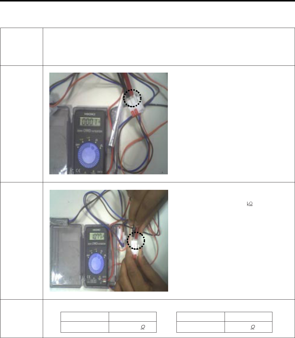
Function - Controller assembly is consist of 2 kinds of part those are fuse-m and sensor. we can
decide part is defect or not when we check the resistance.
- Fuse-m can cut off the source when defrost heater operate the unusual high temperature.
-Sensor give temperature information to Micom
How to
Measure
(Fuse-M)
Set a ohmmeter to the 2 housing pin.
Measure the 2 pin connected to Fuse-M.
If the ohmmeter indicate below 0.1ohm
fuse-m is a good condition, But infinitely
great ohm Fuse-M is disconnection
How to
Measure
(Sensor)
Set a ohmmeter to The 2housing pin.
Measure the 2 pin connected to Sensor.
If the ohmmeter indicate 11
(at room
temperature) Sensor is not a defect.
When check the ohm at other temperature
Check the sensor manual.
Standard
Sensor (at room temperature)
Test Point
(1) to (2)
Ressult
11
Fuse-M (at all temperature)
Test Point
(1) to (2)
Ressult
0 ~ 0.1
(1) to (2)
(1) to (2)
Contents Summary of Kenmore Elite 795 71052 01X
- Page 1REFRIGERATOR SERVICE MANUAL CAUTION BEFORE SERVICING THE UNIT, READ THE SAFETY PRECAUTIONS IN THIS MANUAL. Model #s: 795.71052.01* 795.71053.01* 795.71054.01* 795.71056.01* 795.71059.01* 8020�
- Page 2ENTIFICATION ................................................................................................................................................. 5 BLY .......................................................................................................................................
- Page 3ANT - RECONNECT ALL 795.71052.01* 795.71053.01* DING DEVICES 795.71054.01* 795.71056.01* appliance capable of conducting electrical 795.71059.01* unded. If grounding wires, screws, straps, Defrost Thermostat ....................................... 6615JB2005H ashers used to complete a path to ground
- Page 4Description 795.7105* dles A 35 3/8 in dles B 32 7/8 in oor C 29 in with Door Open) D 47 5/8 in of Case E 68 3/8 in of Door Hinge F 69 3/4 in G 35 3/4 in pen 90 deg. w/o handle) H 39 1/4 in pen 90 deg. w/ handle) I 44 1/4 in -4-�
- Page 5O F C E K L M tor Light K Pullout Drawer side) L Durabase Door Bins M Divider or Bin N Door Bins or Bin O Dairy Bin tor Shelves P Water Tank Cover Q Mullion er and Ice Bin) Controlled Crisper ture Controlled rawer Bin -5-�
- Page 6e left refrigerator door: To remove the Right refrigerator door: tube out of the fitting while pressing the the fitting. out the tube, first you have to push the site direction of arrow in the upper picture ut by direction of arrow. Open the door. Remove the top hinge cover screw (1). Lift up the co
- Page 7moval Press gasket into channels on the four remaining crews. sides of door. up carefully. Mullion Replacement 1. Connect wire harness. wire harness. 2. Insert mullion into channel. Inserting mullion assy’ into bracket, door et Removal sket free from gasket channel on the four 3. Assemble 2 screws.
- Page 8tween your doors is uneven, follow the 1) Remove the plastic guide for slides on left side by low to align the doors: unscrewing phillips head screws. ase Grillie. Turn the leveling legs (CCW) to 2) Pull out the cover sensor to disassemble using tools o lower the height of the front of the shown in
- Page 9rator, or disconnect power at the circuit 1. Remove the upper and lower Caps by using a move top shelf or shelves. flat screwdriver, and ator Compartment Lamp remove 2 screws. (Figure 3) crews. 2. Disconnect the lead wire nds with your both hands and pull it on the bottom position. o remove it. he c
- Page 10funnel by pulling rward. lade screwdriver de hole of the embly dispenser” 3-11 FUNNEL REPLACEMENT ooks of the bottom 1) Pull up and out on the dispenser cover to remove. 2) Remove 2 screws. 3) Disconnect the wire harness. 4) Replace in reverse order. ttom side of the embly, dispenser” the picture, a
- Page 11out on the dispenser cover to remove. the wire harness. funnel. everse order. 3-15 ICE CORNER DOOR REPLACEMENT 1) Loosen the front screw as shown in the picture. 2) Lift up the hinge with one hand. 3) Pull out the Ice Corner Door with the other hand. UCT MOTOR REPLACEMENT e Housing of the Cap Duct M
- Page 12stainless screws marked in the picture the cover, and taped in place. If this harness is loose it will not allow the motor housung assembly to fit flush to the door liner. ottom of motor cover assembly and pull it out wire harness from wall of compartment. In-door motor - 12 -�
- Page 13dles, as shown in the picture. 1) Insert the Ice Bin, slightly tilting it to avoid touching the Icemaker. (Especially, Ice-Detecting Sensor) r part slightly. Bin out slowly. - 13 -�
- Page 14w Steps to Remove the freezer door. Step 2) Remove the lower basket. ve the two screws from the guide rails Step 4) Lift the freezer door up to unhook it from the rail rom each side). support and remove. Pull both rails to full extension. Remove the gear from the left side first by releasing the tab
- Page 15all the right side gear into the clip. the rail into the right side gear. Gears do not Step 3) Insert the rail into the left side gear, and insert the o be perpendicular to each other. gear into the clip. il system will align itself by pushing the rails Step 5) Reinstall the freezer door by insertin
- Page 16water. Then separate the water line from the 1) Using a short screwdriver, loosen one SCREW in DRAIN PIPE ASSEMBLY and one connected to the MOTOR COVER. MOTOR COVER e Mechanical Cover and Valve Screw. 2) Pull and separate the FAN ASSEMBLY and MOTOR anical Cover turning counterclockwise based on the
- Page 17l the drawer out to full extension. the drawer up, then pull it straight out. tly tilt up the front and insert the drawer into the frame and push it back into place. - 17 -�
- Page 18E-Linear compressor is run by mechanical part design or intakes low temperature and low pressure through automatically varying the cooling power. The vaporator of the refrigerator and compresses main parts consist of compressor and Sub PCB which -temperature and high-pressure gas. It then controls t
- Page 19PWB ASSEMBL ASSEMBLYY, SMARTT BUZZER SMAR PWB ASSEMBLY ASSEMBL Y, AMBIENT LED - 19 -�
- Page 20: When you check the Resistance values, be sure to turn off the power. And wait for the voltage-discharge sufficiently. rs before the error : Press the Ultra ICE button and Freezer button aneously 3 hours after the error : All errors, except for "Er rt", "Er SS", (except for Icing sensor)", "Er gF",
- Page 21MFG Picture CON1 CON8 CON6 002701 CON5 .02~) CON2 CON4 CON3 CON10 CON203 173902 .02~) 48Page CON201 CON2 - 21 -�
- Page 22No Picture y PCB 768601 .02~) CON104 CON102 CON101 CON1 PCB 070704 .02~) CON2 - 22 -�
- Page 23Checking flow Result & SVC Action Check for a loose connection. Check the Blue/White to Blue/White. Result SVC Action 0 Short Change the sensor Open Replace the refrigerator Check the Temp and Normal resistance (Table-1)
(1) To (2) Result -22°F °C 40 -13°F °C 30 -4°F °C - Page 24Checking flow Result & SVC Action Check for a loose connection. Check the White to White. Result SVC Action 0 Short Change the sensor Open Replace the refrigerator Check the Temp and Normal resistance (Table-2)
(1) To (2) Result 23°F °C 38 32°F °C 30 41°F °C 24 50°F °C 1 - Page 25Checking flow Result & SVC Action Check for a loose connection. Check the Blue to Blue. Result SVC Action 0 Short Change the sensor Open Replace the refrigerator Check the Temp and Normal resistance (Table-1)
(1) To (2) Result -22°F °C 40 -13°F °C 30 -4°F °C 23 5°F °C 17 14°F ° - Page 26Checking flow Result & SVC Action Check for a loose connection. Check the Orange to Orange. Result SVC Action 0 Short Change the sensor Open Replace the refrigerator Check the Temp and Normal resistance (Table-3) Check the Brown to Brown.
(1) To (2) Result -22°F °C 40 -13°F °C - Page 27Checking flow Result & SVC Action Check the Door gasket. Part Result SVC Action Check the Defrost control part. 0 Go to the 3 Fuse-M Change Fuse-M Fuse Def Def 34~42 Go to the 3 M Sensor Heater Change Fuse-M Def 0 Go to the 3 Sensor OFF Replace product Def Heater nput Test 3 Mode. Push the button 3
- Page 28Checking flow Result & SVC Action Reset the unit and nput Test 1 Mode. Push the button 1 time) Open the freezer door and Check the air Status SVC Action low. While an error code is displayed, No windy Go to 3 the fan is not working. Windy Go to 4 Check the Fan motor. Rotate fan using your hand. It f
- Page 29Checking flow Result & SVC Action Reset the unit and nput Test 1 Mode. Push the button 1 time) Open the refrigerator door and Check the Status SVC Action ir flow. While an error code is displayed, No windy Go to the 3,4 the fan is not working. Windy Go to the 5 Check the Connector Tip Frozen caused
- Page 30Checking flow Result & SVC Action Reset the unit and nput Test 1 Mode. Push the button 1 time) Check the fan rotating. Status SVC Action While an error code is displayed, No windy Check motor the fan is not working. Windy Go to the 4 Check the Fan motor and surrounding. Rotate fan using your hand. I
- Page 31Checking flow Result & SVC Action Check the loose connection. Check the Red to White Red. Result SVC Action 12 VDC Go to the 3 Check the Hinge Other (loose connection)
Change the Main PCB Check the Orange to Brown. Result SVC Action 0 or 5 VDC Change the Display PCB Other Go to the 4 - Page 32Checking flow Result & SVC Action Check the loose connection. Check the Black to White. Lever s/w Result SVC Action While pushing the lever S/W) 112 ~ 116 VAC Go to the 3 Pushing Other Change PCB Not 0 ~2 VAC Go to the 3 pushing Other Change PCB
Check the RED to White Red. Lever s/w Result SV - Page 33Checking flow Result & SVC Action Check the loose connection. Check the Sky Blue to White. Lever s/w Result SVC Action While pushing the lever S/W) 112 ~ 116 VAC Go to the 3 Pushing Other Change PCB Not 0 ~2 VAC Go to the 3 pushing Other Change PCB
Check the RED to White Red. Lever s/w Result - Page 34Checking flow Result & SVC Action Check the loose connection. Check the Purple to White. Lever s/w Result SVC Action While pushing the lever S/W) 112 ~ 116 VAC Go to the 3 Pushing Other Change PCB Not 0 ~2 VAC Go to the 3 pushing Other Change PCB
Check the Blue to Gray. Lever s/w Result SVC A - Page 35Checking flow Result & SVC Action Check the Freezer door switch. If feel sticky, Change the door s/w. Check the door S/W resistance. Status Result SVC Action 0 Go to the 3 Normal not Change door S/W Push Infinity Go to the 3 S/W Change door S/W Check the Black to Sky blue. Status Result SVC Action 5
- Page 36Checking flow Result & SVC Action Check the Refrigerator door switch. If feel sticky, Change the door s/w. Check the door S/W resistance. Status Result SVC Action 0 Go to the 3 Normal not Change door S/W Push Infinity Go to the 3 S/W Other Change door S/W Check the Black to Orange. Status Result SVC
- Page 37Checking flow Result & SVC Action Check the sensor resistance. Temperature Result 23°F °C 38 32°F °C 30 41°F °C 24 50°F °C 19.5
59°F °C 16 The sensor is determined by the temperature. For example, 30 indicates 32°F. Reset the unit and nput Test 1 Mode. Push the button 1 time) Open the fresh f - Page 38Checking flow Result & SVC Action Damper checking method. Test Damper nputting TEST Mode, SVC Action Mode State Check the damper and PCB. 1 Mode Open Damper is normal. 2 Mode Closed (Check the 1,2 Not Change the damper mode working Point Result SVC Action 270 ~330 It’s normal (1) to (2) (3) (1) Othe
- Page 39Checking flow Result & SVC Action Check the sensor resistance. (1) To (2) Result -22°F °C 40 -13°F °C 30 -4°F °C 23 5°F °C 17
14°F °C 13 The sensor is determined by the temperature. 23°F °C 10 For example, 23 indicates -4°F. 32°F °C 8 Reset the unit and nput Test 1 Mode. Push the button 1 tim - Page 40Checking flow Result & SVC Action Check the sensor resistance. Temperature Result 23°F °C 38 32°F °C 30 41°F °C 24
50°F °C 19.5 The sensor is determined by 59°F °C 16 the temperature. For example, 30 indicates 32°F. Reset the unit and nput Test 1 Mode. Push the button 1 time) Open the refrige - Page 41o make TEST MODE push the test button on the Main PCB, the refrigerator will be enter the TEST MODE. * 1 time : Comp / Damper / All FAN on (All things displayed) * 2 times : Damper closed (22 22 displayed) * 3 times : Forced defrost mode (33 33 displayed) Main PWB remove Terminal Position Assurance
- Page 42TEMP RESISTANCE VOLTAGE -39°F (-40°C) 73.29 4.09 V -30°F (-35°C) 53.63 3.84 V -21°F (-30°C) 39.66 3.55 V -13°F (-25°C) 29.62 3.23 V -4°F (-20°C) 22.33 2.89 V 5°F (-15°C) 16.99 2.56 V 14°F (-10°C) 13.05 2.23 V 23°F (-5°C) 10.10 1.92 V 32°F (0°C) 7.88 1.63 V 41°F (5°C) 6.19 1.38 V 50°F (10°C) 4.91 1.1
- Page 43TEMP RESISTANCE VOLTAGE -39°F (-40°C) 225.1 4.48 V -30°F (-35°C) 169.8 4.33 V -21°F (-30°C) 129.3 4.16 V -13°F (-25°C) 99.30 3.95 V -4°F (-20°C) 76.96 3.734 V 5°F (-15°C) 60.13 3.487 V 14°F (-10°C) 47.34 3.22 V 23°F (-5°C) 37.55 2.95 V 32°F (0°C) 30 2.67 V 41°F (5°C) 24.13 2.40 V 50°F (10°C) 19.53 2
- Page 44RNING HIGH VOLTAGE PWB cover Step 2) Check for blinking frequency of LED, PWB If compressor is normal, it does not blink : Refer to the next page to find out what actions to take according to how many times LED blink - 44 -�
- Page 45LED operating condition Cause Service guideline 1.After resetting o - time repetiton PCB part power, check if it is defect running normal (piston 2.If the same overrun) symptom arises after on - off - on - on - off - on - on - off repeating the first action, replace PCB 1.After resetting power, chec
- Page 46027 nding a signal to the fan, the MICOM checks the BLDC fan lock status. If there is no feedback signal from the BLDC fan, motor stops for 10 seconds and then is powered again for 15 . To determine that there is a fan motor malfunction, cess is repeated 3 times. If the fan motor is determined to be
- Page 47- Controller assembly is consist of 2 kinds of part those are fuse-m and sensor. we can decide part is defect or not when we check the resistance. - Fuse-m can cut off the source when defrost heater operate the unusual high temperature. - Sensor give temperature information to Micom Set a ohmmeter t
- Page 48Sheath heater is a part for defrost. All heating wire is connected to only one line. So we can decide part is defect or not when we check the resistance. (1) (2) Set a ohmmeter connect to The 2 housing pin. Measure the 2 pin connected to Sheath Heater. If the ohmmeter indicate (V°øV)/Watt=R is good
- Page 49The heater is designed to prevent the raising dew from door. 1 3 2 6 4 5 7 8 9 Test Point Ressult (1) to (2) 2.3 ~ 2.9 - 49 -�
- Page 50The switch sense if the door open or close. - When the door open, lamp on. - When the door open, the switch give information to Micom. When the door open, internal contact operate on and off moving plunger of door switch up and down.
- Page 51- Dispenser DC Motor : When customer push the dispenser button, Pull duct door and abstract from ice bank. (1) (2) Dispensor DC Motor Dispenser DC Motor Test Points Result (1) to (2) 9.9 ~ 12.1 - 51 -�
- Page 52The In-door motor of AC motor assembly pushes ices to the dispenser. < In-door Motor > < In-door Motor > 1 Take out the male 1 Take out the male housing from housing from female housing female housing 2 Measure the 2 Measure the resistance between resistance between (1) and (2) (1) and (3) (1) (2) (
- Page 53The damper supplies the cold air at freezer room to chillroom by using the damper’s plate. Chillroom is colder than before when damper’s plate is open. When damper’s plate is close, chillroom’s temperature will rise. < Damper Circuit > 1 Blue 1 Blue 2 Red 3 White 3 White 3 Yellow Check the 1 , 3 < e
- Page 54The lamp socket connect cover lamp assembly to lamp. The lamp socket fix lamp and unite lamp and cover lamp assembly. The lamp socket supply electric source to lamp also. (1) (2) (3) (4) Check the resistance between connector of housing and connector of lamp socket. It means check whether or not app
- Page 55Flow Sensor (in machine room) Count the water quantity from city water to water filter in refrigerator Flow Sensor (in machine room) Test Points Result Red wire to Black wire 4 ~ 30 - 55 -�
- Page 56tion tag provides compressor model, refrigerant, serial number and safety approval Compressor Label 1. Compressor Model FC75LANE Operating Type Series name A : A-Inverter DLF/FA/FB E : E-Inverter Displacement Rated Voltage ex)90=9.0 /stroke & Frequency - M : 220V 50/60Hz Application Category - N : 1
- Page 57Step 1) Start up - Half stroke interval for first 30 seconds. Step 2) Ramp up - Stroke increases every 0.8sec until maximum stroke length is reached (about 3 min, 15 sec) Step 3) CVCF interval - 180V / 60Hz Step 1) Start up - Half stroke interval for first 20 seconds. Step 2) Ramp up - Stroke increa
- Page 58M (Intelligent Power Module) converts the 230V DC to 230V AC. ted AC power can be regulated to any required voltage and frequency. E-Inverter FC75LANE A-Inverter wo PCB located behind the PCB cover. FC90LANA main PCB, and the other is the driver PCB ompressor. e voltage at locations on the connector
- Page 59FC90LANA FC75LANE r Spec. Capacitor Spec. F 5% 550V/10uF 5% N/C Po N/C Co r Po : Power mon Co : Common Connecting N/C : No Connecting ressor Winding Resistance Check Compressor Winding Resistance Check 6 ~ 8 Ω Between Po and Co 6 ~ 8 Ω Between Po and Co ompressor NOTE : Any Terminal to Ground should
- Page 60T POINTS TO BE CHECKED REMEDY • Is the power cord unplugged from the outlet? • Plug into the outlet. • Check if the power switch is set to OFF. • Set the switch to ON. • Check if the fuse of the power switch is shorted. • Replace the fuse. • Measure the voltage of the power outlet. • If the voltage
- Page 61ooting Chart TEMPERATURE STATE OF STATE OF THE OF THE E REMARKS THE UNIT EVAPORATOR COMPRESSOR IAL Freezer Low flowing sound of A little higher than • Refrigerant level is low due AGE compartment and Refrigerant is heard ambient to a leak. Refrigerator don't and frost forms in temperature. • Normal
- Page 62“Not Cooling” Complaint All components operating, No airflow problems, Not frosted up as a defrost problem problem has been isolated to sealed system area Partial Frost None Pattern? Equalization Equalization Test Test ry Fast Very Slow Very Slow Fast Very Fast fficient Partial Complete pressor Rest
- Page 63Power On Start Position • Adjusts Ice Tray to Start Position with power on. Icemaking • Waits until water becomes ice. Mode For cold air circulation, Ice tray will be on a slightly tilt one hour after ice-making mode begins. Atilt ice tray Ice Tray on a slightly tilt Full Ice means icemaker’s normal
- Page 64aking Mode Mode begins right after the ice tray fills with water. aits until water becomes ice in the ice tray. g sensor checks if the ice bin is full every 2min. est Mode min, since icemaker begun icemaking mode, Icemaker starts to twist the ice tray to drop ices into the Ice bin. on, at least 1day
- Page 65nit and Ice-detecting sensor Diagnosis er unit and Ice-detecting sensor is programmed to be diagnosed. procedure step by step to check to see if icemaker and Ice-detecting sensor is working normally. aker Unit Ice-detecting sensor Test Switch aker Unit Diagnosis) switch (located on the bottom of the
- Page 66e bin from compartment 2. Close both of the Fresh 3. Wait for 3min. Food doors. 4. Open the Freezer drawer. 5. Press and hold the Door Alarm and Refrigerator Temp. Buttons at the same time. is shown on the display after the procedure above, Ice-detecting sensor is normal. shown on the display after
- Page 67ion ppliance is plugged in, it is set to 37°F for Refrigerator and 0°F for freezer. ust the Refrigerator and the Freezer control temperature by pressing the ADJUST button. ower is initially applied or restored after a power failure, it is set to Control temperature Previously. t press any button aft
- Page 68his function for quick freezing. ress the Ultra Ice Button, the Ultra ICE ICON will be gain. ction automatically turns off after a fixed time passes. nser use selection water or ice. ress the Water Button, the Water selected. ress the Ice button, the Cube/Crush selected in order. up in the dispenser
- Page 69e of this function is to intensify the cooling speed of freezer and to increase the amount of ice. election switch is pressed, selection/release, the Icon will turn ON or OFF. power outage and the refrigerator is powered on again, Ultra ICE will be canceled. this function, press the Ultra ICE key an
- Page 70tarts each time the COMPRESSOR running time Betwee 7~50 hours. wer on or for restoring power, defrosting starts when the compressor running time reaches 4 hours. tops if the sensor temperature reaches 46.4°F(8°C) or more. If the sensor doesn’t reach 46.4°F(8°C) in 1 efrost mode is malfunctioning. (R
- Page 71625A 616G 616D 623B S31 616J 616F 627B S31 S31 27A 619A S32 619E 603B -1-�
- Page 72624D 402A S11 503D 624C 503G 500P S01 624A 409D 158A 103B 271B S11 S01 103A S03 B01 207A 120A 402A 145A 610D 406D 120C 282G B01 405G 120B 329B 405E S02 410J 405C 271D 405F S10 0A 145B 405D 500H 404B 405H 313A S11 405I 282F 262B S11 S14 406B 302B B02 262H 400A 105A 249D B02 18A 249C 316B 317A S14 408
- Page 73-3�
- Page 74-4�
- Page 75133B 145C 131A 136C 136B 133A 133B 132P 145F 237C 136A -5-�
- Page 76141C 141B 141C 141B 141A 141A 141C 141B 141B 141C 141D 154A 161C 151A 161B 151B 146E 161A 162B 145D 162A -6-�
- Page 77233B 241C 241B 233A 231A 235A 212G 241K B06 B06 241D 241G 241D 312B 241E B06 B06 243D 619B 603B 243A 244A 244A 615A 603C 262E 262C 250A 250F 250H 250B 200A 249E 201A 249P 250B B06 B06 212D 249J 203A 249F 249K -7-�
- Page 78-8�
- Page 79276G 276F 278B 278F 402C 276B 275A 500C 276A 278C 281A 278D 405A 279J 279A 501A 500J 276J -9-�
- Page 80630J 612A 630F 630B 630C 600A 611A 630A 630H 630D 606A 630E 630Q 630G - 10 -�
- Page 32Checking flow Result & SVC Action Check the loose connection. Check the Black to White. Lever s/w Result SVC Action While pushing the lever S/W) 112 ~ 116 VAC Go to the 3 Pushing Other Change PCB Not 0 ~2 VAC Go to the 3 pushing Other Change PCB