Samsung Rs2640 Page 17
Workshop Manuals
17
● When the power is applied,currents will be rectified via B and DC360V will be generated at the both terminals of
the capacitor (C001). The Top-Switch (TNY268P)will be automatically switched to the optimum state according
to the secondary load conditions. When currents flow between Top-S/W D and S (5PIN~7PIN),there will be
currents generated i n the TRANS and the currents i nduced to the TRANS upon power off between D and S
will be transferred to the secondary.By repeating the above process, 12V will be maintained at the secondary
C108 and it will be supplied to the display relay. Also, 5V will be generated at the C110 and it will be supplied to
the sensor and operate the main PCB.
OPERATION PRINCIPLES BY PARTS OF CIRCUIT
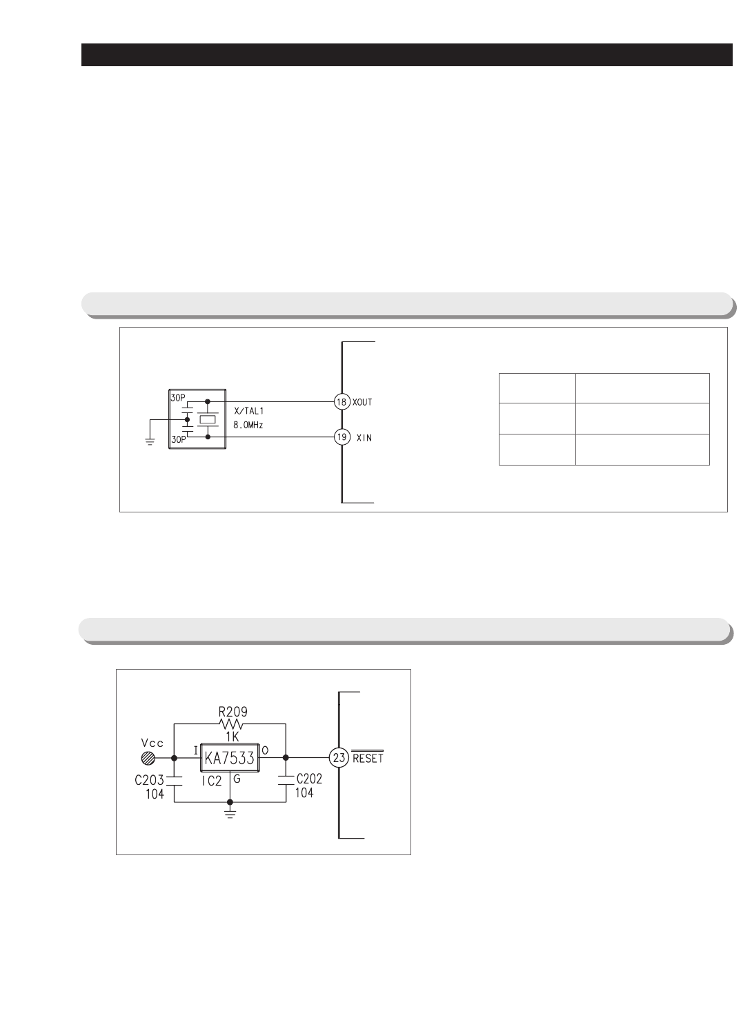
5-2) OSCILLATION CIRCUIT
● It is an Oscillation Circuit for synchronism clock generation and time calculation on the information sending &
receiving of the MICOM internal logic elements and when specifications for Resonator change, the timing
system of MICOM changes resulting in errors. (Rated parts must be used)
Terminal Oscillation Frequency
Xin(#19)
Xout(#18)
8.0MHz
8.0MHz
5-3) RESET CIRCUIT
● RESET Circuit allows the whole program to go back
to the initial setting by initializing parts such as the
RAM in MICOM with the power supply into MICOM or
with an instant power failure.
Upon the power supply, the reset terminal voltage
becomes "LOW" for several tens of ㎲ compared to
Vcc voltage(DC 5V) at MICOM, and it maintains
"HIGH"(Vcc Voltage) during normal operation.
But, when Vcc drops down to 3.4~3.7V, the reset
terminal voltage becomes "LOW".
Contents Summary of Samsung Rs2640
- Page 1SAMSUNG Home Appliance Service SIDE-BY-SIDE REFRIGERATOR Model: RS2*3* RS2*Z* RS2*2* RS2*Y* RS2*1* RS2*X* RS2640 RS26VU
- Page 2WARNING IMPORTANT SAFETY NOTICE The service guide is for service men with adequate backgrounds of electrical, electronic, and mechanical experience. Any attempt to repair a major appliance may result in personal injury and property damage. The manufacturer or dealer cannot be responsible for the int
- Page 3Contents 1. Safety instruction on services ······························ 4 2. Warranty information ···································5 3. Mechanical Disassembly ·································6 4. Circuit Diagram ······································15 5. Operation Principles By Parts Of Circui
- Page 41. Safety Instructions on Service ●Unplug the refrigerator before making any repair or any replacement. Avoid the electric shock. ●Use the rated components on the replacement. Check the correct model number, rated voltage, rated current, operating temperature and so on. ●On repair, be sure that the
- Page 52. Warranty information SAMSUNG REFRIGERATOR LIMITED WARRANTY TO ORIGINAL PURCHASER This SAMSUNG brand product, as supplied and distributed by Samsung Electronics America, Inc. (SAMSUNG) and delivered new, in the original carton to the original consumer purchaser, is warranted by SAMSUNG against man
- Page 63. Mechanical Disassembly 3-1) Refrigerator Disassembly Control Panel ········································ 7 Door Handle ········································· 7 Door Gasket ········································· 7 Refrigerator Door Light Switch ······························· 7 Refrigerat
- Page 73. Mechanical Disassembly 3-1) Refrigerator Disassembly Control Panel Door Gasket 1. Insert a flat-blade screwdriver on the slot as shown, The door gasket is a molded gasket set into a and unlock the tabs. channel located in the door liner. 2. Disconnect the wire connector. 1. Open the door. 2. Gras
- Page 8Mechanical Disassembly Refrigerator Light The refrigerator light is located in the upper portion of refrigerator. 1. Pull the tip on the cover. Gallon Door Bin The door bins allow storage of perishable items. 1. Push the bin up and slide it out. Tempered Glass Shelf These shelves allow the storage o
- Page 9Mechanical Disassembly Damper in the Refrigerator Refrigerator Thermistor 1. Pull out the screw cap and remove the screw. 2. Remove the lamp cover by unlocking the tabs The refrigerator thermistor is located inside of the and pulling the cover down. upper light cover of the refrigerator. 3. Remove t
- Page 10Mechanical Disassembly 3-2) Freezer Disassembly Door Bin in Freezer The door bins allow storage of perishable items. 1. Push the bin up and slide it out. Freezer Shelf The shelves slide out for easy access for frozen items. 1. Slide the shelf out until it reaches its stop. Freezer Door Light Switch
- Page 11Mechanical Disassembly Ice Dispenser & Ice Maker top of the liner, and slide the ice maker in. 5. Tighten the screws (2) of the ice maker support. The ice dispenser is located in the upper portion of the freezer. This assembly stores ice made by the icemaker and dispenses ice. FRONT LOCKING TAB 1. L
- Page 12Mechanical Disassembly Freezer Light Evaporator Cover in Freezer The freezer light is located in the bottom of the 1. Remove screw (6). auger motor case. The light is covered by an opaque 2. Remove the assy cover multi fre. cover. 3. Remove the assy cover supt motor fre. 1. Remove the screw and the
- Page 13Mechanical Disassembly Evaporator in Freezer Evaporator is located in the bottom of freezer to produce cold air driven across the evaporator coils. 1. Take off the ductwork in Freezer. 2. Disconnect the wire connector (Heater, Bimental, and Thermistor). 3. Desolder the inlet and outlet tubes. 4. Rem
- Page 14Mechanical Disassembly 3-3) Machine Compartment Disassembly Machine Compartment & Electric Box 1. Disconnect the power cord of the refrigerator. 2. Remove the fixed screws (6) of compressor cover. Condenser Fan 3. Slide up and take off the compressor cover to The condenser Fan is located in the midd
- Page 154. CIRCUIT DIAGRAM 4-1) Circuit Diagram (RS2*1*,RS2*2*,RS2*3*) 4-2) Circuit Diagram (RS2640, RS26VU) 15
- Page 165. OPERATION PRINCIPLES BY PARTS OF CIRCUIT 5-1) POWER RS2*3*, RS2*2*, RS2*1* Terminal Oscillation Frequency ● Vcc(DC 5V) MICOM POWER AND SENSORS << BLDC BLDC MOTOR POWER(NOT USE) +12V(DC 12V) RELAY,PANEL POWER ● When turned on, rectified AC voltage which is stepped down on 2nd transformer flows bet
- Page 17OPERATION PRINCIPLES BY PARTS OF CIRCUIT ● When the power is applied,currents will be rectified via B and DC360V will be generated at the both terminals of the capacitor (C001). The Top-Switch (TNY268P)will be automatically switched to the optimum state according to the secondary load conditions. Wh
- Page 18OPERATION PRINCIPLES BY PARTS OF CIRCUIT 5-4) EEPROM DETECTION CIRCUIT ● A semiconductor memory EEPROM stores data remembering previous settings regardless of power-off, which are indispensable especially in power fluctuating areas. Also, EEPROM sets and uses other options in principle. 5-5) DOOR SW
- Page 19OPERATION PRINCIPLES BY PARTS OF CIRCUIT Category Door DOOR S/W Contact Point MICOM PORT NO MICOM INPUT CLOSE CLOSE "LOW" F #49 OPEN OPEN "HIGH" CLOSE CLOSE "LOW" R #50 OPEN OPEN "HIGH" RS2640, RS26VU 1) If R-Door is opened, the contact point of the door switch (4-3) becomes open, and the current of
- Page 20OPERATION PRINCIPLES BY PARTS OF CIRCUIT 5-6) TEMP SENSING CIRCUIT RS2*3*, RS2*2*, RS2*1* RS2640, RS26VU 1) Sensor uses a thermistor which has a temp coefficient of negative resistance and controls resistance. When the heat goes up, the resistance gets down and vice versa. R302, 4, 6, 9 and C301~C30
- Page 21OPERATION PRINCIPLES BY PARTS OF CIRCUIT Temp to Resistance of Sensor & MICOM PORT Voltage Sensor CHIP : PX41C Standard Temp. Resistance(Ω) Voltage(V) Temp. Resistance(Ω) Voltage(V) Temp. Resistance(Ω) Voltage(V) Temp. Resistance(Ω) Voltage(V) -50 °C/-58.0°F 153319 4.694 -19°C/-2.2°F 30752 3.773 12°
- Page 22OPERATION PRINCIPLES BY PARTS OF CIRCUIT 5-7) DAMPER CIRCUIT RS2*3*, RS2*2*, RS2*1* 1) The temperature of R-room is controlled by opening and closing of damper with stepping motor, supplying & blocking cold air. 2) TA7774P (IC07) operates the damper. TA7774P is the driver IC only for step motor. If
- Page 23OPERATION PRINCIPLES BY PARTS OF CIRCUIT 1) The temperature of R-room is controlled by opening and closing of damper with stepping motor, supplying & blocking cold air. 2) TA7774P (IC08) operates the damper. TA7774P is the driver IC only for step motor. If the regular signal is provided to TA7774P f
- Page 24OPERATION PRINCIPLES BY PARTS OF CIRCUIT 2) DISPLAY OPERATION Like the signal diagram below, Micom sends “ high ” signal through MICOM 6 terminals of NO #1→ 2 → 3 → 4 → 5 → 6 for 2ms every 12ms. This signal goes to output terminal via input terminal of IC5 (KID65783AP or TD62783AP). Output wave alwa
- Page 25OPERATION PRINCIPLES BY PARTS OF CIRCUIT RS2640, RS26VU 1) Main PCB processes most of the load control for electronic refrigerators. 2) Compressor, F-Room, defrost heater, and other functions are controlled with relay. 3) For example, to operate compressor, MICOM 29 pin outputs high (5V) signal whic
- Page 26OPERATION PRINCIPLES BY PARTS OF CIRCUIT 5-10) ICE MAKER OPERATION CIRCUIT 1) The ice maker circuit above is to control the ice maker kit installed on the F room. 2) This circuit is the hardware to control ejection and horizontal positioning, ice making temperature detection and full icing detection
- Page 27OPERATION PRINCIPLES BY PARTS OF CIRCUIT 5-11) OPTION Circuit ● This circuit operates with the initial power on, uses DIODE (1N4148) or JUMPER WIRE. To modify option circuit, Power must be turned off before modification and turned on after the modification. Refer to the table below, the default fact
- Page 28OPERATION PRINCIPLES BY PARTS OF CIRCUIT 5-12) BLDC MOTOR Circuit(RS2640, RS26VU) 1) This model has adopted a BLDC motor to reduce power consumptions and it is used for all of the F-Room, the R-Room and the Unit Compartment. (This motor driving circuit is the common circuit used in other models.) 2)
- Page 296. Illustrated Parts Catalog. 6-1) Freezer TYPE POWER C 115V, 65HZ 1-15 P 127V, 60HZ 2-3 2-4 2 Q 230V, 50HZ 2-2 2-5 1-14 17 1-22 2-9 2-10 1-12 1-21 2-6 1-10 1-13 1-4 1-11 2-1 2-11 1-6 1-19 2-7 1-9 2-13 1-5 2-15 1-20 2-16 1-7 2-12 2-14 1-8 1-2 1-3 2-18 2-17 2-8 18 1-18 1 1-17 1-1 1-16 3 4 4-1 4-3 8 4
- Page 30Illustrated Parts Catalog. ■ Parts List of Freezer OPTION NO CODE-NO PART NAME RS2*11 RS2*21 RS2*31 RS2*30 Spec RS2*X* RS2*Y* RS2*Z* 1 DA97-02058C ASSY TRAY-ICE BUCKET O O O 1 DA97-02058D ASSY TRAY-ICE BUCKET O 1-1 DA63-02008A COVER-ICE BUCKET O O O O 1-2 DA61-01721A FIXER-NUT O O O O 1-3 DA61-01664
- Page 31Illustrated Parts Catalog. ■ Parts List of Freezer OPTION NO CODE-NO PART NAME Spec RS2*11 RS2*21 RS2*31 RS2*30 RS2*X* RS2*Y* RS2*Z* 4-5 DA63-02183A COVER SENSOR O O O O 5 DA97-02045A ASSY COVER-MULTI FRE O O O O 5-1 DA63-02009A COVER MULTI, FRE O O O O 5-2 DA62-00702A INS-MULTI, FRE O O O O 5-3 DA3
- Page 32Illustrated Parts Catalog. ■ Parts List of Freezer OPTION NO CODE-NO PART NAME RS2*11 RS2*21 RS2*31 RS2*30 Spec RS2*X* RS2*Y* RS2*Z* 15-6 DA63-02028A COVER-HEATER SUB O O O O 15-7 DA63-02182A COVER-HEATER O O O O DA47-00154A HEATER-GLASS O O O O 15-8 DA47-00154B HEATER-GLASS Power Type:Q DA47-00154D
- Page 33Illustrated Parts Catalog. 6-2) Refrigerator 8 1 8-1 8-2 2 2-1 8-3 2-2 8-4 3 8-6 3-2 8-5 3-1 9 8-7 10 4 4-2 11 12 4-1 11-1 11-2 12-1 12-2 15 5 14 6 6-1 6-3 6-2 13 7 7-1 16 17 7-3 7-2 33
- Page 34Illustrated Parts Catalog. ■ Parts List of Refrigerator OPTION NO CODE-NO PART NAME RS2*11 RS2*21 RS2*31 RS2*30 Spec RS2*X* RS2*Y* RS2*Z* 1 DA67-01020A SHELF REF-INSERT O(2) O(1) O(2) PP(INSERT) 1 DA97-02068A ASSY SHELF REF FOLD O(1) 1 DA97-02048A ASSY-SHELF REF UPP O(3) Fabricating 1 DA67-01014A SH
- Page 35Illustrated Parts Catalog. 6-3) Cabinet 5 6 8 9 3 4 7 2 13 12 11 35 10 14 14-1 14-1-1 14-1-2 14-1-3 14-1-4 15 14-2-1 14-2 14-2-3 14-2-2 14-2-4 14-2-5 14-2-6 32 14-3 16 31 17 33 18 25 26 26-3 26-1 29 26-2 27-6 24-1 19 24-3 34 20 27 21 27-1 27-3 24 22 27-2 27-4 24-2 23 30 27-5 28 31
- Page 36Illustrated Parts Catalog. ■ Parts List of Cabinet OPTION NO CODE-NO PART NAME Spec RS2511 RS2521 RS2531 RS2530 RS2611 RS2621 RS2631 RS2630 1 DA90-02102A ASSY CABINET FORM O O O O O O O O DA90-02102B O O O O O O O O 2 DA61-01650A HINGE-UPP O O O O DA61-01709A O O O O 3 DA63-01997A COVER-HINGE UPP O
- Page 37Illustrated Parts Catalog. ■ Parts List of Cabinet OPTION NO CODE-NO PART NAME Spec RS2511 RS2521 RS2531 RS2530 RS2611 RS2621 RS2631 RS2630 27 DA97-01763A ASSY HINGE LOW-R O O O O O O O O 27-1 6003-001435 SCREW-TAPTITE O O O O O O O O 27-2 DA61-01608A HINGE-LOW REF O O O O O O O O 27-3 6021-001125 N
- Page 38Illustrated Parts Catalog. 6-4) Disassembly of Freeze Door 8-2 8-3 8-4 8-5 8-6 9-9 9-4 9-11 8 9-10 9 9-8 11 9-7 8-1 9-1 9-6 10 9-5 9-3 9-2 1 14 14-3 12 2 6 14-1 15 5 14-2 7 13 3 4 38
- Page 39Illustrated Parts Catalog. ■ Parts List of Freezer Door OPTION NO CODE-NO PART NAME Spec RS2511 RS2521 RS2531 RS2530 RS2611 RS2621 RS2631 RS2630 RS25X* RS25Y* RS25Z* RS26X* RS26Y* RS26Z* 1 DA91-01838A ASSY DOOR FOAM FRE O O O O S/WHITE 1 DA91-01838B ASSY DOOR FOAM FRE O O O O STAINLESS PLATINUM 1 DA
- Page 40Illustrated Parts Catalog. ■ Parts List of Freezer Door OPTION NO CODE-NO PART NAME Spec RS2511 RS2521 RS2531 RS2530 RS2611 RS2621 RS2631 RS2630 RS25X* RS25Y* RS25Z* RS26X* RS26Y* RS26Z* 8-4 DA61-01614A SUPPORT-KNOB TOUCH O O O O O 8-5 DA61-01716A CASE-COVER CONTROL B O O O 8-5 DA61-01611A CASE-COVE
- Page 41Illustrated Parts Catalog. 6-5) Disassembly of Refrigerator Door 2 6 1 5 12 10 12-3 13 12-1 12-2 7 11 9 2 8 4 41
- Page 42Illustrated Parts Catalog. ■ Parts List of Refrigerator Door OPTION NO CODE-NO PART NAME Spec RS2511 RS2521 RS2531 RS2530 RS2611 RS2621 RS2631 RS2630 RS25X* RS25Y* RS25Z* RS26X* RS26Y* RS26Z* 1 DA91-01840A ASSY DOOR FOAM REF O O O O S/WHITE 1 DA91-01840B ASSY DOOR FOAM REF O O O O STAINLESS PLATINUM
- Page 43Appendix Ⅰ(Reference for circuit diagnostics) Ref.1) Measure Load Terminals RS2*3*, RS2*2*, RS2*1* Turn off Power, disassemble Housing connected to MAIN PCB CN70,71,72 and measure followings LOAD TERMINALS PCB CASE VALUE DEFECTS OTHERS 1) DEFROST HEATER 0Ω THERMAL FUSE, HEATER, WIRE SHORT THERMAL 2)
- Page 44Appendix Ⅰ(Reference for circuit diagnostics) Turn on Power and check status of Relay & Driving Circuit by checking followings according to load operation. LOAD RELAY TERMINALS VALUE WHEN IT IS DIFFERENT FROM MEASURED VALUE RY76 /RY75 SUPPLY CN71⑪∼⑨ VOLTAGE(SV) RY76 CONTACT SHORT,FAULTY DRIVING CIRC
- Page 45Appendix Ⅰ(Reference for circuit diagnostics) Turn off the power, disassemble the Housing connected to the MAIN PCB CN70, 71 & 72 and measure the followings LOAD TERMINALS PCB CASE VALUE DEFECTS OTHERS 1) DEFROST HEATER 0Ω THERMAL FUSE, HEATER, WIRE SHORT VALUE FOR 2) ICE PIPE HEATER CN71 ⑦ & ① ∞Ω N
- Page 46Appendix Ⅰ(Reference for circuit diagnostics) Ref.2) Measure Sensor Terminals RS2*3*, RS2*2*, RS2*1* Check after disassembling connected to MAIN PCB CN30 &CN32 Because it is NTC TYPE Sensor, risistance decreases as temp increases 1. Measure resistance between CN30 ⑧ and ⑨ for R-Sensor. 2. Measure re
- Page 47Appendix Ⅰ(Reference for circuit diagnostics) Ref. 3) SERVICE PARTS LIST FOR CIRCUIT NO ITEM SPEC CODE NO OTHERS ELECTRONIC (RS2*11) DA41-00219A ELECTRONIC (RS2*21) DA41-00219B ELECTRONIC (RS2*30) DA41-00219C 1 PBA-MAIN ELECTRONIC (RS2*31) DA41-00219D ELECTRONIC (RS2640) DA41-00252A Only 115V ELECTR
- Page 48272, Oseon-Dong, Kwangsan-Gu, Kwangju-City, Korea, 506-253 TEL : 82-62-950-6810, 6811 FAX : 82-62-950-6829 - This Service Manual is a property of Samsung Electronics Co., Ltd. Any unauthorized use of Manual can be punished under applicable International and/or domestic law. - © Samsung Electronics C