Frigidaire Bf Page 23
Workshop Manuals
6-19
Component Teardown
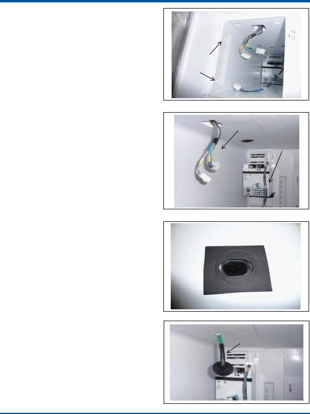
Figure 6-58
Figure 6-74
Ice Maker Housing Removal
Disconnect power from the unit before performing this
procedure.
1. After completing the Ice Maker Removal Procedure,
remove the screws at the front of the Housing. Figure
6-56.
NOTE: One or both of the side screws may not be used.
2. With all the screws removed, pull the front end of the
housing body downward about an inch and feed the har-
nesses up through the square hole. Figure 6-57.
3. Pull the cover forward and out of the unit. The wiring
harness coming from the rear of the housing will slide
out the back of the housing. Figure 6-57.
Fill Funnel Removal and Replacement
Disconnect power from the unit before performing this
procedure.
The Fill Funnel is the black, plastic part that is inserted
into the top of the Ice Maker Housing. It serves to direct
the incoming water directly into the ice maker.
1. After completing the Ice Maker Housing Removal
procedure, remove the foam gasket covering the funnel.
Figure 6-58.
2. Pull the Funnel out of the housing.
3. To replace the Funnel, insert the funnel into the ob-
long hole in the top of the Housing. Be sure the long end
of the Funnel is oriented toward the rear of the housing.
IMPORTANT: The slotted opening in the funnel must
not be squeezed or deformed in any way.
4. Place a new gasket over the Funnel. The gasket must
be centered over the funnel so the opening of the funnel
is not obstructed.
Fill Tube Removal and Replacement
Disconnect power from the unit before performing this
procedure.
The 1/4” green fill tube from the water valve is adapted
to a 5/16” green tube approximately two feet above the
valve on the back of the unit.
1. After completing the Ice Maker Housing Removal pro-
cedure, disconnect the larger green tube from the in-line
connector.
NOTE: There will likely be some water that will spill
from the green tube. Be prepared to collect or wipe.
2. Push the tube forward about an inch into the back,
top of the unit. The tube will now protrude into the fresh
food compartment far enough to be gripped. Figure
6-59.
3. From the front of the unit, pull the tube downward
and out of the unit.
Figure 6-56
remove two (2) screws
Figure 6-57
this harness will
slide out the back
feed this harness up through
the hole in the housing
Figure 6-59
black grommet must be
positioned as shown to
prevent kinking of the
tube in the conduit
Contents Summary of Frigidaire Bf
- Page 1All About Servicing Bottom Freezer Refrigerator FOR TRAINING CLASS USE ONLY ™ Electrolux Major Appliances, North America 10200 David Taylor Drive Charlotte, NC 28262 Publication #5995556437 February 2011
- Page 2Basic Information Model Number Matrix FG HB 23 44 L F BRAND PRODUCT CAPACITY FEATURE YEAR OF COLOR CATEGORY LEVEL INTRODUCTION Brand FG – Frigidaire Gallery FP – Frigidaire Professional LG – Lowe’s Gallery Product HB – High Efficiency Bottom Freezer Category HN – High Efficiency Non-Dispensing Botto
- Page 3Basic Information Models with Fresh Food Ice Maker NOTE: Features may vary according to model Incandescent Light (select models) Ice Flipper Guide LED Light (select models) Water Bin Ice Filter Maker Dairy Compartment Air Filter Can Rack SpillSafeTM (select models) Shelves SpillSafeTM Flipper Shelve
- Page 4Basic Information Models With Dispenser and Fresh Food Compartment Ice Maker PERFORMANCE DATA NO LOAD & NO DOOR OPENINGS AT 37°/0° CONTROL SETTING Type A with Run/Start Capacitor 65°F (18°C) Ambient 90°F (32°C) Ambient Operating Time 74 to 84% 100% Freezer Temperature -5° to 2° F (-20° to -17° C) -1
- Page 5Basic Information Models With Freezer Compartment Ice Maker And Without Dispenser PERFORMANCE DATA NO LOAD & NO DOOR OPENINGS AT 37°/0° CONTROL SETTING Variable Speed Compressor 65°F (18°C) Ambient 90°F (32°C) Ambient Operating Time 32 to 40% 100% -6° to 6° F -6° to 6° F Freezer Temperature -21° to
- Page 6Electronic Control The purpose of this section is to familiarize the service technician with operation of the user interface and proper function of the electronic control system. This section explains all electronic controls and diagnostics for the unit with the exception of ice maker controls. Ice
- Page 7Electronic Control Pro-Select™ User Interface Display Operation (Dispenser Models) options Figure 3-4. Pro-Select™ User Interface for Dispenser Models Touch an icon (Water/Cube/Crush) to activate the desired power on-off Press and hold for three (3) seconds dispenser mode. to turn off the cooling sy
- Page 8Electronic Control Express-Select™ User Interface Display Operation (Dispenser Models) Figure 3-5. Express-Select™ User Interface for Dispenser Models ice off Press and hold for three (3) seconds air filter Touch to display filter status. Press (Fresh Food to turn the ice maker “ON” or “OFF”. and ho
- Page 9Electronic Control Express-Select™ User Interface Display Operation (Non-Dispenser Models) A red indicator light will be illuminated above most active features. Touch the icon to activate the options below. quick ice Increases the production of ice water filter Press and hold for three (3) seconds t
- Page 10Electronic Control Sabbath Mode Showroom Mode The Sabbath Mode is a feature that disables portions Express-Select™ of the refrigerator and its controls in accordance with To enter, press and hold freezer temperature up (∧) observance of the weekly Sabbath and religious holidays while pressing the fr
- Page 11Electronic Control Alarms Door Ajar If the door has been left open for an extended period of time an alarm will sound and the door ajar indicator will display on the right side of the display. The alarm is turned off by closing the door. The mute sounds key or alarm off key will blink to prompt the
- Page 12Electronic Control Entering System Service Mode Test 8: Water valve (water dispenser test only) NOTE: Place a cup in the dispenser prior to starting this Note: Fresh Food Ice Maker service mode is discussed test to collect the water as both primary and dispenser in section 4 of this manual. valve wi
- Page 13Electronic Control Test 23: Fresh food door Temperature Resistance Chart Freezer Display will show “OP” open when doors are open and “CL” when door is closed. For Negative Temperature Test 24: Freezer door (See Flow Chart 5) Coefficient Thermistors Freezer Display will show “OP” open when door is op
- Page 14Electronic Control Ice and Water Dispense Troubleshooting Guide General Information Diagnosing Ice and Water Dispense Issues 1. During normal operation, certain components can fail via System Service Mode independently with no cascading effect to other ice and 1. Enter service mode water related com
- Page 15Electronic Control Variable Capacity Compressor 2. Remove the lower power board from under the front of the product. (See Section 6 for detailed Electrical Components procedure). You will use connection J2 terminal 3 The new series of very high efficiency compressors are (RED/BLK) and terminal 4 (BL
- Page 16Electronic Control 3. If the voltage checks good, remove the inverter Testing the Compressor from the compressor by removing one screw at the bottom of the inverter that goes through the bracket The compressor has a 3 phase, 4 pole brushless DC welded to the compressor. (See Figure 3-11) Pull motor.
- Page 17Ice Maker The ice maker has a drive motor and gear box assembly in the front section of the ice maker. A bail arm mounted Depending on the Engineering Digit at the end of to the side of the gear box and the flex ice tray are the model number, the product may be equipped with driven off the back of t
- Page 18Ice Maker (Flex Tray Fresh Food Compartment) Ice maker, bail arm, bail arm switch, gear box, are mounted in the front of the ice maker in a snap out housing. The bail arm drops down to check the amount of ice in the bucket and uses the switch to prevent ice harvest when the ice maker bucket is full.
- Page 19Ice Maker (Flex Tray Fresh Food Compartment) About Ice Cube Production There is a thermistor located inside a foam insulation cover under the ice maker flex tray that senses the temperature of the water and the ice tray. The signal from the thermistor is sent to the lower control board of the refrig
- Page 20Ice Maker (Flex Tray Fresh Food Compartment) After pushing ‘power on-off’ to start automatic test or turn on the load, the ice maker control will display The Ice Maker must be turned on before entering the the test result on the freezer two digit display. When Service Mode. Check the ‘ice off’ indic
- Page 21Ice Maker (Flex Tray Fresh Food Compartment) Temperature Resistance Chart For Test 57C: Evaporator Fan Test Negative Temperature Coefficient To start this interactive test, touch ‘power on-off’ to Thermistors activate the fan. Touching ‘power on-off’ again will turn the fan off. The Freezer display
- Page 22Component Teardown Fresh Food Compartment Refrigerated Ice Maker Flex-Tray IMPORTANT NOTE ABOUT ICE MAKER GASKETS: All gasket seals in the ice maker housing assembly are critical to ensure proper management of air flow, moisture and defrost water. Anytime a gasket seal is broken, the affected gasket
- Page 23Component Teardown Ice Maker Housing Removal Disconnect power from the unit before performing this procedure. 1. After completing the Ice Maker Removal Procedure, remove the screws at the front of the Housing. Figure 6-56. NOTE: One or both of the side screws may not be used. remove two (2) screws 2
- Page 24Component Teardown 4. To replace the tube, insert the green end into the opening of the conduit inside the fresh food compart- ment. 5. Push the tube through the conduit and out the back of the unit. remove 3 screws IMPORTANT: Be sure the black portion of the tube is oriented as shown in figure 6-59
- Page 25Component Teardown Auger Motor, Crusher Solenoid, and Fan Disconnect power from the unit before performing this procedure. The Auger Motor is attached with 3 screws driven in from the front of the Air Handler. Note that the top screw is covered by a foam gasket. 1. After completing the Air Handler R
- Page 26Component Teardown Evaporator Housing Removal - continued The liner has a tab that extends down to the drain tube to conduct heat during defrosts to melt any ice accumulation in the drain tube. There is also a piece of aluminum tape that wraps onto the front wall of the Housing. The tape conducts he
- Page 27Component Teardown Evaporator Housing Replacement The “U” shaped gasket Disconnect power from the unit before performing this on the back of the evaporator housing procedure. must be replaced when IMPORTANT: When the Evaporator Housing is re- the evaporator housing moved, (and when the Air Handler i
- Page 28Component Teardown Air Handler Replacement Disconnect power from the unit before performing this align notch with hole in liner procedure. 1. Replace any foam gaskets on the Air Handler that have been damaged. 2. Align the notch in the Evaporator Housing with the top, left screw hole for the Air Han
- Page 29Component Teardown Ice Maker Replacement - continued. proper routing of the harness in 3. As you slide the ice maker onto the shoulder screws, the channel and under the tab you cannot see the two rear screws. Therefore, after installing the ice maker, you must pull down on the two back corners to be