Gr S512Gc Lg Refrigerator Service Manual Page 3
Workshop Manuals
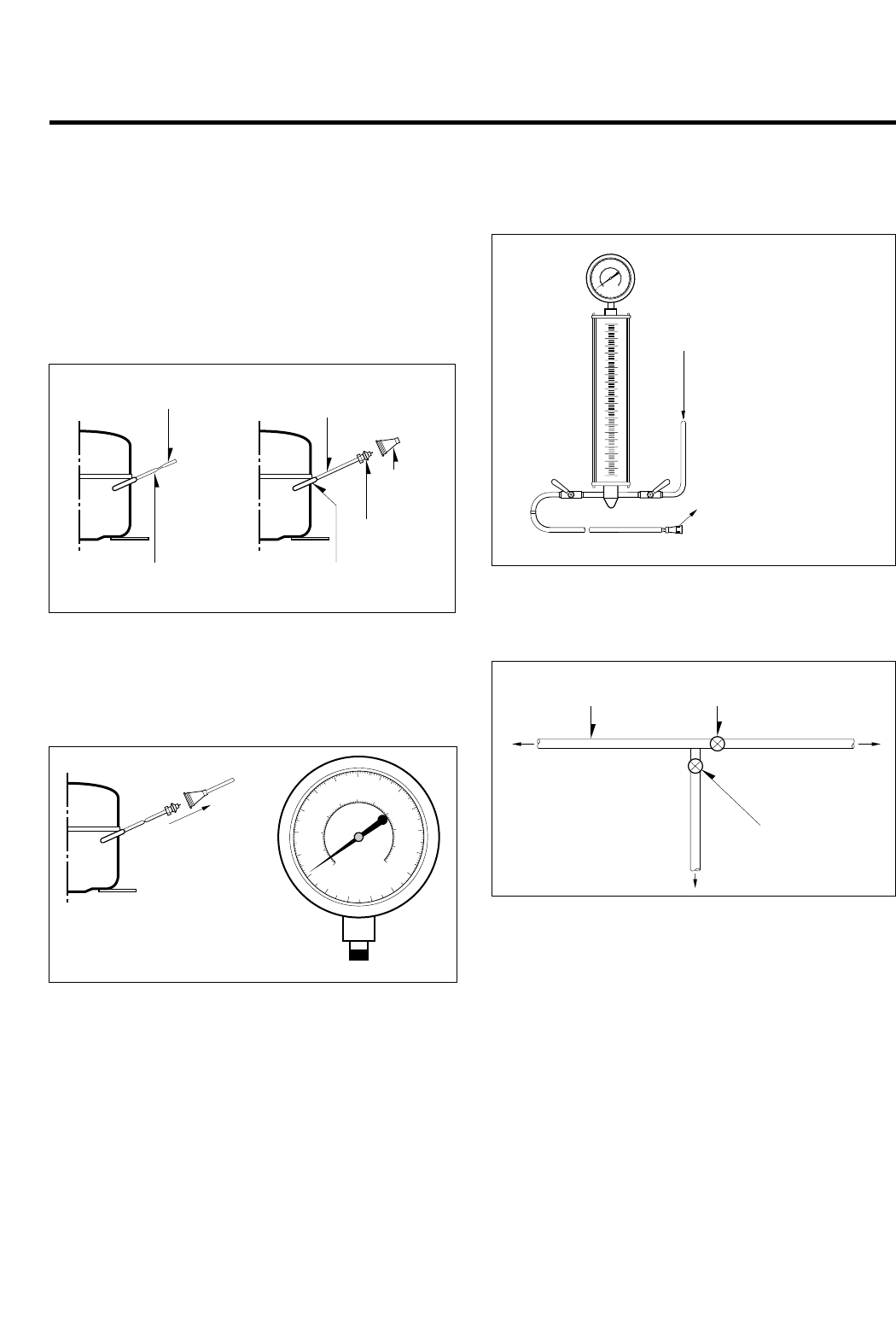
Air Recharging in Compressor
Test the refrigeration by connecting it electrically before
refilling operation. It is necessary to ascertain the function
of the motor-compressor and identify the defects
immediately. If the defects have been found, empty the old
system of eventual R-134a residue by breaking off the end
of the extension piece at its narrow point. (Figure 1)
Replace the filter and any damaged components. Unsolder
and pull off the piece remaining inside the service tube and
then attach an extension completely with male Hansen and
last, solder it to the same tube again. (Figure 2)
It is necessary to execute the soldering operation with
valve open so that the fumes caused by oil residue can
come out freely without blowholes between two tubes
during heating the point to be soldered.
The extension fitted with the male Hansen is connected to
the female fitting of the vacuum pump tube. (Figure 3)
Air evacuating from the system begins so soon as the
pump starts. The refrigeration system must be kept under
vacuum until the reading on the low-pressure gauge
indicates vacuum (0 absolute, -1 atm., -760 mm hg) in any
case it is advisable to keep the pump running for about 30
minutes. (Figure 3)
In case that a considerable leakage occurs and to stop the
vacuum pump will be necessary and add a small quantity
of Freon to the system, if vacuum should not be obtained
(pressure gauge can't fall to 1 atmosphere), start the
refrigeration unit and find the leakage with the special leak-
finder. When the defective soldering point is visible, re-do it
after opening the extension tube valve and reestablishing
the normal outside pressure inside the group.
Because the melted alloy is sucked into the tubes and
block them, the pressure must be rebalanced when
vacuum is in the system in soldering. As soon as the
vacuum operation is over, add the quantity in grams of R-
134a to the refrigerant system. Remember that every
system has an exact quantity of R-134a with a tolerance of
±5 grams that can be added. (Figure 4)
Before performing this operation (if the vacuum pump and
refilling cylinder are connected), make sure that the valve
placed between the vacuum pump and refilling tube are
closed to keep the Freon for adding to the system. (Figure 5)
In addition, check the graduated scale on the cylinder for
the quantity of R-134a to be added, for example, if we
have 750 grams of Freon in the cylinder and must add 165
grams to the group, this amount will be reached when R-
134a has dropped to 585 grams, remembering that the
indicator shows a lower limit of meniscus. Do this after
choosing the scale corresponding to the gas pressure
different scales reported as the same gas pressure
indicated by the pressure gauge on the top of the column.
To make R-134a flow into the system, open the valve
placed at the base of the cylinder and connected to the
filling tube. The amount of Freon cannot be added to the
system all at once because it may cause a blocking of
motor-compressor. Therefore, proceed by adding original
quantity of about 20-30 grams and close the valve
immediately.
The pressure rises and the motor-compressor must start,
sucking the gas and making the pressure go down again.
Regulate the valve again, maintaining the same manner
until reaching to the quantity of R-134a established for the
system being charged. When the system is running, the
suction pressure must be stabilized between 0.30 to 0.6
atmosphere.
SERVICING PRECAUTIONS
- 3 -
POINT TO BE
BROKEN
CHARGE TUBE
EXTENSION
FEMALE
HANSEN
MALE HANSEN
SOLDERING POINTSERVICE TUBE EXTENSION
Figure 1 Figure 2
TO THE VACUUM
PUMP
PRESSURE
GAUGE
Figure 3
TO THE R-134a CYLINDER
TO THE REFRIGERATION
SYSTEM
Figure 4
FILLING OR
CHARGE TUBE
VALVE TO BE OPENED
WHEN REFILLING
VALVE TO BE CLOSED
AFTER VACUUM
TO THE VACUUM PUMP
TO THE REFRIGERATION
SYSTEM
TO THE CHARGE
CYLINDER
Figure 5
Contents Summary of Gr S512Gc Lg Refrigerator Service Manual
- Page 1http://biz.lgservice.com REFRIGERATOR SERVICE MANUAL CAUTION BEFORE SERVICING THE UNIT, READ THE "SAFETY PRECAUTIONS" IN THIS MANUAL. MODEL: GR-S462/GR-S512�
- Page 2CONTENTS SAFETY PRECAUTIONS ....................................................................................................................................................... 2 SERVICING PRECAUTIONS.................................................................................................
- Page 3SERVICING PRECAUTIONS Air Recharging in Compressor vacuum operation is over, add the quantity in grams of R- Test the refrigeration by connecting it electrically before 134a to the refrigerant system. Remember that every refilling operation. It is necessary to ascertain the function system has an ex
- Page 41. SPECIFICATIONS SPECIFICATIONS ITEMS GR-S512Q/GR-S512G GR-S462Q/GR-S462G FREEZER 116 103 NET CAPACITY REFRIGERATOR 297 270 (l) TOTAL 413 373 DIMENSIONS (mm) 680(W) X 758(D) X 1725(H) 680(W) X 708(D) X 1725(H) NET WEIGHT (kg) 74 71 COOLING SYSTEM Fan Cooling TEMPERATURE FREEZER Knob Dial CONTROL RE
- Page 52. PARTS IDENTIFICATION FREEZER COMPARTMENT Lamp Freezer Temperature Control Dial Freezer Door Rack Freezer Shelf Twisting Ice Serve(Option) or General Type Ice Making Egg Storage Rack REFRIGERATOR Wine Rack COMPARTMENT (Option if steel shelf) Deodorizer You can use (Option) this as Chilled Compartm
- Page 63. DISASSEMBLY 3-1 DOOR 3-2 DOOR SWITCH ● Freezer Door 1. To remove the door switch, pull out it with a '—' type 1. Remove the hinge cover by pulling it upwards. driver as shown in (figure 9). 2. Loosen hexagonal bolts fixing the upper hinge to the 2. Disconnect the lead wire from the switch. body a
- Page 76. Disconnect the housing of lead wire. 3-6 LAMP 7. Separate the Fan Assy. 8. Loose 2 screw fixed to the Bracket. FREEZER ROOM LAMP REFRIGERATOR ROOM LAMP 9. Pull out Shroud-F remove the Fan Motor Assy. 10. Separate the Motor Bracket and Rubber. FAN MOTOR SHROUD Figure 16 Figure 17 BRACKET FAN 3-6-1
- Page 84. ADJUSTMENT 4-1 COMPRESSOR 4-2-3 PTC-Applied Circuit Diagram 4-1-1 Role ● According to Starting Method of Motor The compressor inhales low temperature and low pressure gas evaporated from Evaporator of the Refrigerator, and OVERLOAD PROTECTOR condenses this gas to high temperature and high pressur
- Page 94-3 OLP (OVER LOAD PROTECTOR) CONTACTING 4-3-1 Definition of OLP POINT COVER (1) OLP (OVER LOAD PROTECTOR) is attached to Hermetic Compressor and protects Motor by cutting off BIMETAL current in Compressor Motor by Bimetal in the OLP in case of over-rising temperature. (2) When over-voltage flows to
- Page 106. TROUBLESHOOTING 6-1 COMPRESSOR AND ELECTRIC COMPONENTS (Rating Voltage YES 1 Power Source. Remove the PTC-Starter 2 from the Compressor ±10%)? and measure the voltage between Terminal C of Compressor and Terminals 5 or 6 of PTC. YES No Voltage. OLP disconnected? Replace OLP. 5 Check connection co
- Page 116-2 PTC AND OLP Normal operation of Separate the PTC from Observation value is Check another Compressor is Compressor and 220V/50Hz : 22Ω±30% electric components. impossible or poor. measure the resistance 115V/60Hz : 6.8Ω±30% between No. 5 and 6 240V/50Hz : 33Ω±30% 127, 220V/60Hz : (only RSIR Type)
- Page 126-3 ANOTHER ELECTRIC COMPONENTS ▼ Cooling is impossible Compressor Check if current flows to doesn't run. the following Cause. components. a. Thermistor Poor contacting. b. Starting devices Shorted or broken. c. OLP Poor contacting or shorted. d. Compressor coil Coil shorted. Poor contacting Replace
- Page 136-4 SERVICE DIAGNOSIS CHART COMPLAINT POINTS TO BE CHECKED REMEDY Cooling is • Is the power cord unplugged from the outlet? • Plug to the outlet. impossible. • Check if the power S/W is set to OFF. • Set the switch to ON. • Check if the fuse of power S/W is shorted. • Replace a regular fuse. • Measu
- Page 146-5 REFRIGERATING CYCLE ▼ Troubleshooting Chart TEMPERATURE STATE OF STATE OF THE CAUSE OF THE REMARKS THE SET EVAPORATOR COMPRESSOR PARTIAL Freezer and Low flowing sound of A little high • A little Refrigerant LEAKAGE Refrigerator Refrigerant is heard and more than • discharges. don't get cold fros
- Page 15▼ General Control of Refrigerating Cycle NO. ITEMS CONTENTS AND SPECIFICATIONS REMARKS WELDING (1) H 30 ROD (1) • Chemical Ingredients • Recommend H34 containing 34% Ag in the (1) • Ag: 30%, Cu: 27%, Zn: 23%, Cd: 20% • Service Center. (1) • Brazing Temperature: 710~840°C (2) Bcup-2 1 (1) • Chemical
- Page 167. DESCRIPTION OF FUNCTION & CIRCUIT OF MICOM The following description is basically for GR-S462/GR-S512. For the other models, refer to the diagram of the entire PCB circuit. 7-1 FUNCTION 7-1-1 FUNCTION 1. When the appliance is plugged in, it is set to ‘Medium’. Each time the button is pushed, it i
- Page 177-1-2 DEFROSTING 1. The defrosting is performed each time when the total running time of the compressor reaches 7 hours. 2. After the power is turned on (or restored after a power failure), the defrosting starts when the total running time of the compressor reaches 4 hours. 3. When the temperature o
- Page 187-1-5 ERROR DIAGNOSTIC MODE 1. The error diagnostic mode allows the SVC when a fault that may affect the performance of the product occurs while operating the product. 2. Even if the function control button is pushed when an error occurs, the function will not be performed. 3. When the error is clea
- Page 197-2 PCB FUNCTION 7-2-1 POWER CIRCUIT The secondary part of the TRANS is composed of the power supply for the display and relay drive (12Vdc) and that for the MICOM and IC (5Vdc). The voltage for each part is as follows. PART VA 1 CE 2 CE3 VOLTAGE 220 Vac 12 Vdc 5 Vdc VA1 is a part for preventing the
- Page 207-2-2 OSCILLATION CIRCUIT This circuit is to generate the base clock for calculating time and the synchro clock for transmitting data from and to the inside logic elements of the IC1(MICOM). Be sure to use the authentic parts since the calculating time by the IC1 may be changed or it will not work i
- Page 217-2-4 LOAD DRIVE CIRCUIT 1. Load Drive Condition Check Comp, Load Type Defrosting Heater Refrigerator Fan Freezer Fan Motor Measurement Location(IC5) No.13 No.10 No.12 ON 1V or below Condition OFF 12V - 21 -�
- Page 227-2-5 TEMPERATURE SENSOR CIRCUIT The upper CIRCUIT reads REFRIGERATOR temperature and DEF-SENSOR temperature for defrosting into MICOM. OPENING or SHORT state of each TEMPERATURE SENSOR are as follows. SENSOR CHECK POINT NORMAL(-30 °C ~ 50 °C) SHORT-CIRCUITED OPEN Refrigerator Sensor POINT A Voltage
- Page 237-2-7 TEMPERATURE COMPENSATION & OVERCOOLING/UNDERCOOLING COMPENSATION CIRCUIT 1. Refrigerator Temperature Compensation Refrigerator Resistance Temperature Remark (RCR1) Compensation 180 KΩ +2.5 °C Compensation by raising the 56 KΩ +2.0 °C temperature 33 KΩ +1.5°C 18 KΩ +1.0 °C 12 KΩ +0.5 °C 10 KΩ 0
- Page 247-2-8 KEY BUTTON INPUT & DISPLAY LIGHT ON CIRCUIT ➧ The circuit shown above is to determine whether a function control key on the operation display is pushed and to turn on the corresponding function indication LED. The drive type is the scan type. - 24 -
- Page 257-3 RESISTANCE SPECIFICATION OF SENSOR TEMPERATURE SENSOR RESISTANCE OF REFRIGERATOR (DEFROST) SENSOR - 20 ˚C 77 KΩ - 15 ˚C 60 KΩ - 10 ˚C 47.3 KΩ - 5 ˚C 38.4 KΩ 0 ˚C 30 KΩ + 5 ˚C 24.1 KΩ + 10 ˚C 19.5 KΩ + 15 ˚C 15.9 KΩ + 20 ˚C 13 KΩ + 25 ˚C 11 KΩ + 30 ˚C 8.9 KΩ + 40 ˚C 6.2 KΩ + 50 ˚C 4.3 KΩ • The re
- Page 267-4 TROUBLE SHOOTING • Replace PCB when no trouble after checking the contents of trouble. CLASSIFICATION STATE OF TROUBLE POINT BE CHECKED CHECKING METHOD CONTENT REMEDY POWER SOURCE 1. All the DISPLAY 1. FREEZER/ FREEZER/REFRIGERATOR POWER SOURCE is poor Certify Fuse. is poor LED OFF REFRIGERATOR
- Page 27CLASSIFICATION STATE OF TROUBLE POINT BE CHECKED CHECKING METHOD CONTENT REMEDY COOLING is poor. REFRIGERATOR 1. FREEZER TEMPERATURE See "FREEZER Certify the attaching state TEMPERATURE is is normal? TEMPERATURE is poor". of DOOR. poor. 2. Cool air of FAN MOTOR is Certify the amount of cool air FAN
- Page 287-5 MAIN PWB ASSEMBLY AND PARTS LIST 7-5-1 MAIN PWB ASSEMBLY - 28 -�
- Page 297-5-2 REPLACEMENT PARTS LIST - 29 -�
- Page 307-5-3 PWB ASSEMBLY, DISPLAY AND PARTS LIST - 30 -�
- Page 317-6 PWB DIAGRAM - 31 -�
- Page 32REF. TEMP. CONTROL - 32 -�
- Page 338. EXPLODED VIEW ▼ The parts of refrigerator and the shape of each part are subject to change in different localities. ▼ Capacitors and fuse are optional parts. ▼ : Optional parts. * 1) Freezer Shelf -Plastic : 149A -Steel : 136C, 136D 103B 2) Ice Maker 301A - Twist : 110B, 125A, 125H, 131A 281A - S
- Page 34405C 405A 330B 404A 329A 332A * 149D * 110B * 125A * 131A * 136C * 125H * 125J * 149A * 136D 149B 140A 149C * 149C * 136A * 149C 136B * 149C * 136A * 136B 154A 155B 151A - 34 -�
- Page 35205A 203A 200A 201A 201A 205A * 212G * 212G 212A 212C 212A 212C 235A 210A 210A 241A 230A 233A 231A 237A 233B 231A 233B 241C 244A 241A 244C 244A 244C 241D 210A 210A - 35 -�