Gr S512Gc Lg Refrigerator Service Manual Page 8
Workshop Manuals
4-1 COMPRESSOR
4-1-1 Role
The compressor inhales low temperature and low pressure
gas evaporated from Evaporator of the Refrigerator, and
condenses this gas to high temperature and high pressure
gas, and then plays delivering role to Condenser.
4-1-2 Composition
The Compressor is Composed of Compressor Apparatus
compressing gas, Compressor Motor moving Compressor
Apparatus and Case protecting Compressor Apparatus
and Motor. There are PTC-Starter, and Over Load
Protector (OLP) in the Compressor outside.
On the other
hand, because the Compressor consists of 1/1000mm processing
precision components and is sealed after producing without dust
or humidity, deal and repair with care.
4-1-3 Note to Use
(1) Be careful not to allow over-voltage and over-current.
(2) No Strike
If applying forcible power or strike (dropping or careless
dealing), poor operation and noise may occur.
(3) Use proper electric components appropriate to the
Compressor.
(4) Note to Keep Compressor.
If Compressor gets wet in the rain and rust in the pin of
Hermetic Terminal, poor operation and poor contact
may cause.
(5) Be careful that dust, humidity, and flux due to welding
don't inflow in Compressor inside in replacing
Compressor. Dust, humidity, and flux due to welding
which inflows to Cylinder may cause lock and noise.
4-2 PTC-STARTER
4-2-1 Composition of PTC-Starter
(1) PTC (Positive Temperature Coefficient) is no-contact
semiconductor starting device which uses ceramic
material and the material consists of BaTiO
3.
(2) The higher the temperature is, the higher resistance
value becomes . These features are used as starting
device of Motor.
4-2-2 Role of PTC-Starter
(1) PTC is attached to Hermetic Compressor used for
Refrigerator, Show Case and starts Motor.
(2) Compressor for household refrigerator applies single-
phase induction Motor.
For normal operation of single-phase induction motor, in
the starting operation flows in both main coil and sub-
coil. After the starting is over, the current is cut off in
subcoil. The proper features of PTC play the above all
roles. So, PTC is used as a starting device of motor.
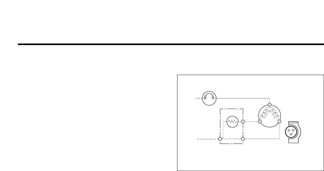
4-2-3 PTC-Applied Circuit Diagram
● According to Starting Method of Motor
4-2-4 Motor Restarting and PTC Cooling
(1) For restarting after power off during normal
Compressor Motor operation, plug the power cord after
5 min. for pressure balance of Refrigerating Cycle and
PTC cooling.
(2) During normal operation of Compressor Motor, PTC
elements generate heat continuously. Therefore,
if PTC isn't cooled for a while after power off, Motor
can't operate again.
4-2-5 Relation of PTC-Starter and OLP
(1) If power off during operation of Compressor and power
on before PTC is cooled, (instant shut-off within 2 min.
or reconnect a power plug due to misconnecting),
PTC isn't cooled and a resistance value grows. As a
result, current can't flow to the sub-coil and Motor can't
operate and OLP operates by flowing over current in
only main-coil.
(2) While the OLP repeats on and off operation about 3-5
times, PTC is cooled and Compressor Motor performs
normal operation.
If OLP doesn't operate when PTC is not cooled,
Compressor Motor is worn away and causes circuit-
short and fire. Therefore, use a proper fixed OLP
without fail.
4-2-6 Note to Use PTC-Starter
(1) Be careful not to allow over-voltage and over-current.
(2) No Strike
Don't apply a forcible power or strike.
(3) Keep apart from any liquid.
If liquid such as oil or water inflows into PTC,
PTC materials it may break due to insulation
breakdown of material itself.
(4) Don't change PTC at your convenience.
Don't disassemble PTC and mold. If damaging to
outside of PTC-starter, resistance value alters and poor
starting of compressor motor may cause.
(5) Use a properly fixed PTC.
4. ADJUSTMENT
- 8 -
PTC STARTER
HERMETIC
TERMINAL
COMPRESSOR
MOTOR
C
M
S
M
3
6
5
S
PTC
OVERLOAD PROTECTOR
RSIR
Figure 20
Contents Summary of Gr S512Gc Lg Refrigerator Service Manual
- Page 1http://biz.lgservice.com REFRIGERATOR SERVICE MANUAL CAUTION BEFORE SERVICING THE UNIT, READ THE "SAFETY PRECAUTIONS" IN THIS MANUAL. MODEL: GR-S462/GR-S512�
- Page 2CONTENTS SAFETY PRECAUTIONS ....................................................................................................................................................... 2 SERVICING PRECAUTIONS.................................................................................................
- Page 3SERVICING PRECAUTIONS Air Recharging in Compressor vacuum operation is over, add the quantity in grams of R- Test the refrigeration by connecting it electrically before 134a to the refrigerant system. Remember that every refilling operation. It is necessary to ascertain the function system has an ex
- Page 41. SPECIFICATIONS SPECIFICATIONS ITEMS GR-S512Q/GR-S512G GR-S462Q/GR-S462G FREEZER 116 103 NET CAPACITY REFRIGERATOR 297 270 (l) TOTAL 413 373 DIMENSIONS (mm) 680(W) X 758(D) X 1725(H) 680(W) X 708(D) X 1725(H) NET WEIGHT (kg) 74 71 COOLING SYSTEM Fan Cooling TEMPERATURE FREEZER Knob Dial CONTROL RE
- Page 52. PARTS IDENTIFICATION FREEZER COMPARTMENT Lamp Freezer Temperature Control Dial Freezer Door Rack Freezer Shelf Twisting Ice Serve(Option) or General Type Ice Making Egg Storage Rack REFRIGERATOR Wine Rack COMPARTMENT (Option if steel shelf) Deodorizer You can use (Option) this as Chilled Compartm
- Page 63. DISASSEMBLY 3-1 DOOR 3-2 DOOR SWITCH ● Freezer Door 1. To remove the door switch, pull out it with a '—' type 1. Remove the hinge cover by pulling it upwards. driver as shown in (figure 9). 2. Loosen hexagonal bolts fixing the upper hinge to the 2. Disconnect the lead wire from the switch. body a
- Page 76. Disconnect the housing of lead wire. 3-6 LAMP 7. Separate the Fan Assy. 8. Loose 2 screw fixed to the Bracket. FREEZER ROOM LAMP REFRIGERATOR ROOM LAMP 9. Pull out Shroud-F remove the Fan Motor Assy. 10. Separate the Motor Bracket and Rubber. FAN MOTOR SHROUD Figure 16 Figure 17 BRACKET FAN 3-6-1
- Page 84. ADJUSTMENT 4-1 COMPRESSOR 4-2-3 PTC-Applied Circuit Diagram 4-1-1 Role ● According to Starting Method of Motor The compressor inhales low temperature and low pressure gas evaporated from Evaporator of the Refrigerator, and OVERLOAD PROTECTOR condenses this gas to high temperature and high pressur
- Page 94-3 OLP (OVER LOAD PROTECTOR) CONTACTING 4-3-1 Definition of OLP POINT COVER (1) OLP (OVER LOAD PROTECTOR) is attached to Hermetic Compressor and protects Motor by cutting off BIMETAL current in Compressor Motor by Bimetal in the OLP in case of over-rising temperature. (2) When over-voltage flows to
- Page 106. TROUBLESHOOTING 6-1 COMPRESSOR AND ELECTRIC COMPONENTS (Rating Voltage YES 1 Power Source. Remove the PTC-Starter 2 from the Compressor ±10%)? and measure the voltage between Terminal C of Compressor and Terminals 5 or 6 of PTC. YES No Voltage. OLP disconnected? Replace OLP. 5 Check connection co
- Page 116-2 PTC AND OLP Normal operation of Separate the PTC from Observation value is Check another Compressor is Compressor and 220V/50Hz : 22Ω±30% electric components. impossible or poor. measure the resistance 115V/60Hz : 6.8Ω±30% between No. 5 and 6 240V/50Hz : 33Ω±30% 127, 220V/60Hz : (only RSIR Type)
- Page 126-3 ANOTHER ELECTRIC COMPONENTS ▼ Cooling is impossible Compressor Check if current flows to doesn't run. the following Cause. components. a. Thermistor Poor contacting. b. Starting devices Shorted or broken. c. OLP Poor contacting or shorted. d. Compressor coil Coil shorted. Poor contacting Replace
- Page 136-4 SERVICE DIAGNOSIS CHART COMPLAINT POINTS TO BE CHECKED REMEDY Cooling is • Is the power cord unplugged from the outlet? • Plug to the outlet. impossible. • Check if the power S/W is set to OFF. • Set the switch to ON. • Check if the fuse of power S/W is shorted. • Replace a regular fuse. • Measu
- Page 146-5 REFRIGERATING CYCLE ▼ Troubleshooting Chart TEMPERATURE STATE OF STATE OF THE CAUSE OF THE REMARKS THE SET EVAPORATOR COMPRESSOR PARTIAL Freezer and Low flowing sound of A little high • A little Refrigerant LEAKAGE Refrigerator Refrigerant is heard and more than • discharges. don't get cold fros
- Page 15▼ General Control of Refrigerating Cycle NO. ITEMS CONTENTS AND SPECIFICATIONS REMARKS WELDING (1) H 30 ROD (1) • Chemical Ingredients • Recommend H34 containing 34% Ag in the (1) • Ag: 30%, Cu: 27%, Zn: 23%, Cd: 20% • Service Center. (1) • Brazing Temperature: 710~840°C (2) Bcup-2 1 (1) • Chemical
- Page 167. DESCRIPTION OF FUNCTION & CIRCUIT OF MICOM The following description is basically for GR-S462/GR-S512. For the other models, refer to the diagram of the entire PCB circuit. 7-1 FUNCTION 7-1-1 FUNCTION 1. When the appliance is plugged in, it is set to ‘Medium’. Each time the button is pushed, it i
- Page 177-1-2 DEFROSTING 1. The defrosting is performed each time when the total running time of the compressor reaches 7 hours. 2. After the power is turned on (or restored after a power failure), the defrosting starts when the total running time of the compressor reaches 4 hours. 3. When the temperature o
- Page 187-1-5 ERROR DIAGNOSTIC MODE 1. The error diagnostic mode allows the SVC when a fault that may affect the performance of the product occurs while operating the product. 2. Even if the function control button is pushed when an error occurs, the function will not be performed. 3. When the error is clea
- Page 197-2 PCB FUNCTION 7-2-1 POWER CIRCUIT The secondary part of the TRANS is composed of the power supply for the display and relay drive (12Vdc) and that for the MICOM and IC (5Vdc). The voltage for each part is as follows. PART VA 1 CE 2 CE3 VOLTAGE 220 Vac 12 Vdc 5 Vdc VA1 is a part for preventing the
- Page 207-2-2 OSCILLATION CIRCUIT This circuit is to generate the base clock for calculating time and the synchro clock for transmitting data from and to the inside logic elements of the IC1(MICOM). Be sure to use the authentic parts since the calculating time by the IC1 may be changed or it will not work i
- Page 217-2-4 LOAD DRIVE CIRCUIT 1. Load Drive Condition Check Comp, Load Type Defrosting Heater Refrigerator Fan Freezer Fan Motor Measurement Location(IC5) No.13 No.10 No.12 ON 1V or below Condition OFF 12V - 21 -�
- Page 227-2-5 TEMPERATURE SENSOR CIRCUIT The upper CIRCUIT reads REFRIGERATOR temperature and DEF-SENSOR temperature for defrosting into MICOM. OPENING or SHORT state of each TEMPERATURE SENSOR are as follows. SENSOR CHECK POINT NORMAL(-30 °C ~ 50 °C) SHORT-CIRCUITED OPEN Refrigerator Sensor POINT A Voltage
- Page 237-2-7 TEMPERATURE COMPENSATION & OVERCOOLING/UNDERCOOLING COMPENSATION CIRCUIT 1. Refrigerator Temperature Compensation Refrigerator Resistance Temperature Remark (RCR1) Compensation 180 KΩ +2.5 °C Compensation by raising the 56 KΩ +2.0 °C temperature 33 KΩ +1.5°C 18 KΩ +1.0 °C 12 KΩ +0.5 °C 10 KΩ 0
- Page 247-2-8 KEY BUTTON INPUT & DISPLAY LIGHT ON CIRCUIT ➧ The circuit shown above is to determine whether a function control key on the operation display is pushed and to turn on the corresponding function indication LED. The drive type is the scan type. - 24 -
- Page 257-3 RESISTANCE SPECIFICATION OF SENSOR TEMPERATURE SENSOR RESISTANCE OF REFRIGERATOR (DEFROST) SENSOR - 20 ˚C 77 KΩ - 15 ˚C 60 KΩ - 10 ˚C 47.3 KΩ - 5 ˚C 38.4 KΩ 0 ˚C 30 KΩ + 5 ˚C 24.1 KΩ + 10 ˚C 19.5 KΩ + 15 ˚C 15.9 KΩ + 20 ˚C 13 KΩ + 25 ˚C 11 KΩ + 30 ˚C 8.9 KΩ + 40 ˚C 6.2 KΩ + 50 ˚C 4.3 KΩ • The re
- Page 267-4 TROUBLE SHOOTING • Replace PCB when no trouble after checking the contents of trouble. CLASSIFICATION STATE OF TROUBLE POINT BE CHECKED CHECKING METHOD CONTENT REMEDY POWER SOURCE 1. All the DISPLAY 1. FREEZER/ FREEZER/REFRIGERATOR POWER SOURCE is poor Certify Fuse. is poor LED OFF REFRIGERATOR
- Page 27CLASSIFICATION STATE OF TROUBLE POINT BE CHECKED CHECKING METHOD CONTENT REMEDY COOLING is poor. REFRIGERATOR 1. FREEZER TEMPERATURE See "FREEZER Certify the attaching state TEMPERATURE is is normal? TEMPERATURE is poor". of DOOR. poor. 2. Cool air of FAN MOTOR is Certify the amount of cool air FAN
- Page 287-5 MAIN PWB ASSEMBLY AND PARTS LIST 7-5-1 MAIN PWB ASSEMBLY - 28 -�
- Page 297-5-2 REPLACEMENT PARTS LIST - 29 -�
- Page 307-5-3 PWB ASSEMBLY, DISPLAY AND PARTS LIST - 30 -�
- Page 317-6 PWB DIAGRAM - 31 -�
- Page 32REF. TEMP. CONTROL - 32 -�
- Page 338. EXPLODED VIEW ▼ The parts of refrigerator and the shape of each part are subject to change in different localities. ▼ Capacitors and fuse are optional parts. ▼ : Optional parts. * 1) Freezer Shelf -Plastic : 149A -Steel : 136C, 136D 103B 2) Ice Maker 301A - Twist : 110B, 125A, 125H, 131A 281A - S
- Page 34405C 405A 330B 404A 329A 332A * 149D * 110B * 125A * 131A * 136C * 125H * 125J * 149A * 136D 149B 140A 149C * 149C * 136A * 149C 136B * 149C * 136A * 136B 154A 155B 151A - 34 -�
- Page 35205A 203A 200A 201A 201A 205A * 212G * 212G 212A 212C 212A 212C 235A 210A 210A 241A 230A 233A 231A 237A 233B 231A 233B 241C 244A 241A 244C 244A 244C 241D 210A 210A - 35 -�