Traulsen Page 12
Workshop Manuals
COMPONENT FUNCTION
1. Compressor Pumps refrigerant thru refrigeration system components and compresses the low
pressure vapor into high pressure vapor.
2. Evaporator Fan Draws air across condenser coil to aid in removing heat from the refrigerant and
moves air across compressor to aid in cooling the compressor.
3. Start Capacitor Stores electrical charge which helps start the compressor motor.
4. Run Capacitor Helps keep the compressor motor running after starting.
5. Microprocessor Control Performs the functions of the 1) defrost timer, 2) high limit switch, 3) thermometer and
4) thermostat.
6. Drawer Perimeter Heater Heats drawer opening to prevent condensation from forming.
7. Contactor Relay Controls voltage to compressor motors.
-11-
XI. ELECTRICAL OPERATION (cont’d)
XI. c-COMPONENT FUNCTION:
There are two sensors used inside the cabinet. The rst one is
the Cabinet Sensor that is used to cycle the compressor on and
off at the correct temperature. The cabinet sensor is mounted
through the wall of the evaporator housing on the return side of
the evaporator.
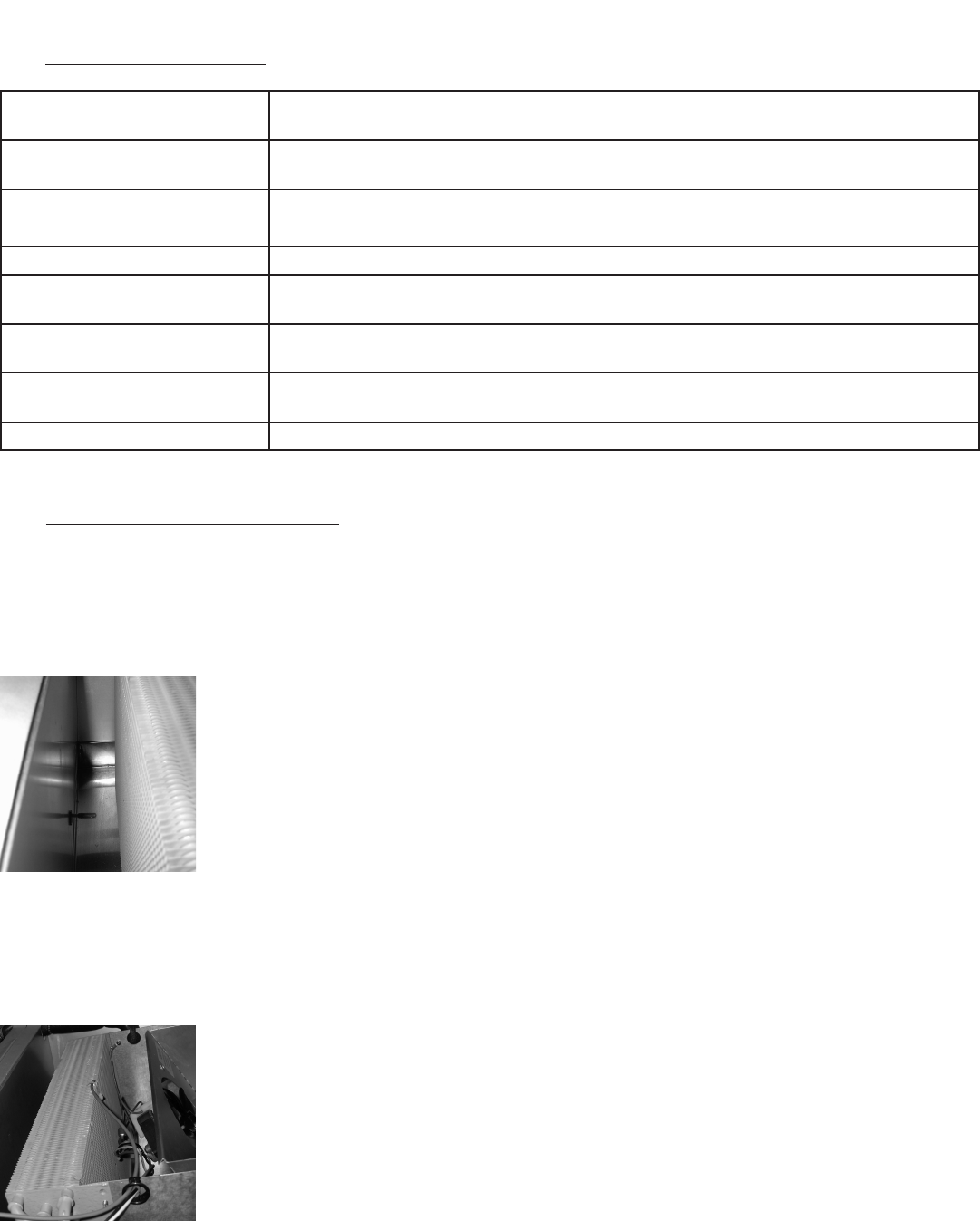
The Evaporator Coil Sensor is to be mounted in the evaporator,
in the center of the coil and fully inserted into the coil until only
the wire is visible and then pinch the ns around the cable to
hold it in place. The part number for the Evaporator Coil Sensor
is 337-60406-02.
The third sensor used is a Liquid Line Sensor. This sen-
sor is to be installed on the liquid line as it comes out
of the condenser coil. The part number for this sensor
is 337-60407-01.
When the condensing temperature reaches 140°F or
greater the control will display “CLN-FIL.” Should the
condensing temperature increase to 160°F the com-
pressor will automatically shut off. When the liquid line
temperature drops below 140°F the compressor will
restart and when the line temperature drops to 120°F
the alarm will reset.
XI. d-INSTALLATION OF THE SENSORS:
Illustration XI. 1
Illustration XI. 2
Contents Summary of Traulsen
- Page 1Traulsen Refrigeration SERVICE MANUAL Instructions For The Troubleshooting And Repair Of Traulsen Full-Size Undercounter Refrigerators and Freezers TU044HT, TU072HT & TU100HT Refrigerator Models TU044LT & TU072LT Freezer Models This manual is prepared for the use of trained Authorized Traulsen Servi
- Page 2TABLE OF CONTENTS I. THE SERIAL TAG Page 1 V. CONDENSER FAN MOTOR OR BLADE Page 4 II. GENERAL INFORMATION Page 2 VI. CONDENSER COIL Page 5 a-Introduction Page 2 VII. EVAPORATOR FAN Page 5 b-Model Designations Page 2 VIII. COMPRESSOR Page 6 c-Wiring Diagram Page 2 IX. WIRING DIAGRAM Page 7 d-Installa
- Page 3II. GENERAL INFORMATION II. a-INTRODUCTION: II. f-TOOL REQUIREMENTS (cont’d): This manual applies to the following models only: ● Refrigeration Guage Manifold ● Refrigeration Reclaiming Equipment TU Series Full-Size Undercounter Refrigerators ● Acetylene Torch TU044HT, TU072HT & TU100HT ● Anti-Stati
- Page 4II. GENERAL INFORMATION (cont’d) II. i-THE MICROPROCESSOR CONTROL: II. m-SPECIFICATIONS-REFRIGERATOR: For detailed information on replacement, repair or adjustment of the INTELA-TRAUL® microprocessor control please refer to it’s TU044HT TU072HT TU100HT manual, form number TR35705 or contact our Serv
- Page 5III. SERVICE ACCESS (cont’d) V. CONDENSER FAN MOTOR OR BLADE III. a-SYSTEM(cont’d): V. a-REPLACEMENT INSTRUCTIONS: To gain full access to the refrigeration system from the Disconnect the electrical power to the machine side, remove the side cover by removing the screws. and follow lockout/tag out pr
- Page 6VI. CONDENSER COIL VII. EVAPORATOR FAN VI. a-REPLACEMENT INSTRUCTIONS: VII. a-REPLACEMENT INSTRUCTIONS: Disconnect the electrical power to the Disconnect the electrical power to the machine and follow lockout/tag out procedures. machine and follow lockout/tag out procedures. This procedure requires
- Page 7VIII. COMPRESSOR VIII. a-COMPRESSOR: Disconnect the electrical power to the machine and follow lockout/tag out procedures. This procedure requires the use of re- frigerants, be certain the work area is well ventilated. Safety goggles and gloves shall be worn since refrig- erants may cause burns to t
- Page 8IX. WIRING DIAGRAM NOTE: Refer to the wiring diagram below (applies to refrigerators and freezers units) for any service work performed by a qualified technician. -7-
- Page 9X. SERVICE PROCEDURES & ADJUSTMENTS Certain procedures in this section require electrical test or measurements while power is applied to the machine. Excercise extreme caution at all times. If test points are not easily accessible, disconnect power, attach test equipment and reapply power to test. X
- Page 10X. SERVICE PROCEDURES & ADJUSTMENTS (cont’d) Certain procedures in this section require electrical test or measurements while power is applied to the machine. Excercise extreme caution at all times. If test points are not easily accessible, disconnect power, attach test equipment and reapply power t
- Page 11X. PROCEDURES & ADJ. (cont’d) XI. ELECTRICAL OPERATION Certain procedures in this section re- XI. a-NORMAL OPERATION: quire electrical test or measurements while power is 1. Conditions applied to the machine. Excercise extreme caution a) Unit connected to correct voltage (check using a volt me- at a
- Page 12XI. ELECTRICAL OPERATION (cont’d) XI. c-COMPONENT FUNCTION: COMPONENT FUNCTION 1. Compressor Pumps refrigerant thru refrigeration system components and compresses the low pressure vapor into high pressure vapor. 2. Evaporator Fan Draws air across condenser coil to aid in removing heat from the refri
- Page 13XII. TROUBLESHOOTING Certain procedures in this section require electrical and refrigeration system test or measurements while power is applied to the machine, exercise extreme caution at all times. If test points are not easily accessible, disconnect power, attach test equipment and reapply power t
- Page 14XIII. SERVICE PARTS LIST NOTE: Part numbers listed are for standard products as currently manufactured. For products manufactured as other than standard, please contact the factory with model and serial number of unit in question. ITEM DESCRIPTION PART NUMBER Casters All Models 6” Adjustable - No Lo
- Page 15XIV. SERVICE ASSISTANCE XIV. a-SERVICE INFORMATION: NOTE: Before calling for service, please check the following: Is the electrical cord plugged in? Is the fuse OK or circuit breaker on? Clean condenser coil Is the power switch on? Reset microprocessor control values to factory defaults. If after ch
- Page 16HOURS OF OPERATION: Monday thru Friday 7:30 am - 4:30 pm CST Traulsen 4401 Blue Moud Road Fort Worth, TX 76106 Phone (800) 825-8220 Fax (817) 740-6757 Website: www.traulsen.com Quality Refrigeration © 2009 Traulsen - All Rights Reserved