Samsung Rf220Nctasr Page 12
Workshop Manuals
14
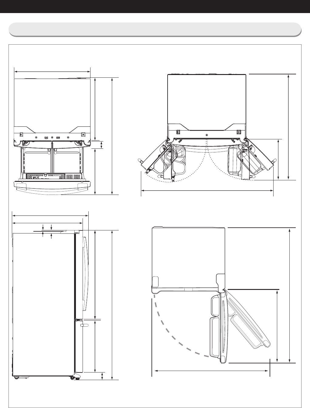
PRODUCT SPECIFICATIONS
30 1/2" (774 mm)
3 3/8" (87 mm)
21 5/8" (549 mm)
39 5/8" (1007 mm)
5/8" (16 mm)
66 3/4" (1697 mm)
1 3/8" (34 mm)
1 3/8" (36 mm)
34 1/4" (872 mm)
36 3/4" (934 mm)
48 5/8" (1234 mm)
29 3/4" (756 mm)
24 5/8" (625 mm)
1 7/8" (48 mm)
53 1/2" (1359 mm)
15 1/4" (387 mm)
46 1/8" (1171 mm)
47” (1194 mm)
30 ¼” (770 mm)
61 1/8” (1554 mm)
RF22*
RL22*
2-3) Dimensions of Refrigerator(RF22*) (Inches)
Contents Summary of Samsung Rf220Nctasr
- Page 1Service Manual RF220NCTASR/AA�
- Page 21. PRECAUTIONS (SAFETY WARNINGS) ●Unplug the appliance before replacing or repairing electrical parts. ⇢ Be careful to avoid electric shock. ●Always use only the correct replacement parts. ⇢ Check the model, rated voltage, rated current and running temperature rating. ●When troubleshooting, verify t
- Page 3PRECAUTIONS (SAFETY WARNINGS) Read all instructions before repairing the product and follow the instructions in order to prevent danger or property damage. Plug out and remove all the items in regrigerator prior to repair. CAUTION/WARNING SYMBOLS DISPLAYED SYMBOLS means "Prohibited". Indicates that
- Page 4PRECAUTIONS (SAFETY WARNINGS) Please let users know following warnings & cautions in detail. Warning & Caution Customers should not store glass Customers should not store narrow Drugs requiring precise bottles of liquid in the freezer or long bottles or food in a small temperatures should not be sto
- Page 5PRECAUTIONS (SAFETY WARNINGS) FLOORING For proper installation, this refrigerator must be placed on a level surface of hard material that is the same height as the rest of the flooring. This surface should be strong enough to support a fully loaded refrigerator, or approximately 286.6 lbs (130 kg).
- Page 62. PRODUCT SPECIFICATIONS 2-1) Specifications .................................................................................................................................................. 9 2-2) Interior Views .....................................................................................
- Page 7PRODUCT SPECIFICATIONS 2-1) Specifications ELECTRICAL SPECIFICATIONS Defrost Control From 12 to 30hrs(comp. run time) Thermo Bimetal Protector 140°F(60°C)(off) 104°F(40°C)(on) Defrost Thermistor(502AT) 50°F(10°C)(off) Electrical Rating AC115V 60Hz 11.6 Amps Maximum Current Leakage 0.25 mA Maximum Gr
- Page 8PRODUCT SPECIFICATIONS 2-2) Interior Views LAMP Vertical Hinged Section Quick-Space Glass Shelf (on Internal Water On e To T uc h Pu re Wa ter some models) Dispenser (RF221**) Door Bins Vegetable & Fruit Drawers Light FZ Ice-Maker Ice Bucket Freezer Drawer Bin Light g QUICK-SPACE GLASS SHELF Vegetab
- Page 9PRODUCT SPECIFICATIONS RF221 RF220 RL225 RL220 Model PANTRY, DISPENSER, PANTRY, AUTO ICE AUTO ICE MAKER BASIC AUTO ICE MAKER MAKER ITEM IMAGE W 29 3/4" (756mm) 29 3/4" (756mm) 29 3/4" (756mm) 29 3/4" (756mm) On Cabinet 30 1/2" (774mm) 30 1/2" (774mm) 30 1/2" (774mm) 30 1/2" (774mm) D W/O Handle 34 1
- Page 10PRODUCT SPECIFICATIONS Items Specification Model RF22* RL22* Model MKV172CL2J Compressor Starting type INVERTER Components for Freezer Oil Charge FREOL - 15 Evaporator Freezer SPLIT FIN TYPE Condenser Forced and natural convection type Dryer Molecular sieve XH-9 Capillary tube (Dia x Length) 0.030 ”
- Page 11PRODUCT SPECIFICATIONS Items Specification Model RF221* RF220* RL225* RL220* Defrost Heater(FRE) Heated at F Defrost 120V, 200W 120V, 200W 120V, 200W 120V, 200W FRENCH Heater - 120V, 10W 120V, 10W - - HEATER ICE PIPE - 12V, 2W 12V, 2W 12V, 2W 12V, 2W Bimetal thermo For Preventing Overheating of 40℃
- Page 1236 3/4" (934 mm) 34 1/4" (872 mm) 1 3/8" (34 mm) 1 3/8" (36 mm) 29 3/4" (756 mm) 24 5/8" (625 mm) 21 5/8" (549 mm) 30 1/2" (774 mm) 39 5/8" (1007 mm) 5/8" (16 mm) 3 3/8" (87 mm) 1 7/8" (48 mm) PRODUCT SPECIFICATIONS 66 3/4" (1697 mm) 53 1/2" (1359 mm) 2-3) Dimensions of Refrigerator(RF22*) (Inches)
- Page 13PRODUCT SPECIFICATIONS 2-4) Optional Material Specification Part Name Part Code AMOUNT ASSY-PACKING SUB DA99-03490L 1 LED LAMP REF DA41-00676G 3 LED LAMP FRE DA41-00676G 1 15�
- Page 14PRODUCT SPECIFICATIONS 2-5) Refrigerant Route in Refrigeration cycle Compressor → Condenser → Hot pipe → Pipe cluster rear → Dryer → Capillary tube → Freezer Evaporator → Suction pipe → Compressor 16
- Page 15PRODUCT SPECIFICATIONS 2-5-1. Operation theory of refrigeration cycle components ■Condenser 1) Role: A device which radiates heat to the outside of the refrigerator. As this heat is dispersed, the high temperature/ high pressure vapor refrigerant changes to a liquid state. 2) Types A. Air-cooling Ty
- Page 16PRODUCT SPECIFICATIONS ■Evaporator 1. Role: As the low pressure liquid refrigerant flowed from capillary absorbs heat inside of the refrigerator, it becomes low pressure gas and refrigerate the foods. 2. Theory: The low pressure refrigerant flowed to evaporator operates cooling which takes ambient e
- Page 17PRODUCT SPECIFICATIONS ※. Influence of moisture ① Moisture precipitation - Blocked by ice ② Refrigerant and reaction ③ Life reduction of oil ④ Acceleration of oxidization ⑤ Copper plating phenomenon ⑥ Gas dissolution by the interaction of synthetic insulating material (insulator) ※. Influence of for
- Page 18PRODUCT SPECIFICATIONS 2-6) Cooling Air Circulation Refrigerator Ice Maker Duct in Fridge Discharge Return Duct Freezer Duct in Freezer Discharge Return Duct In some cases, frost blocks the return hole in freezer and it may cause weak cooling or No ice making. 20�
- Page 193. DISASSEMBLY AND REASSEMBLY 3-1) PRECAUTION .................................................................................................................................................22 3-2) Refrigerator Door ...................................................................................
- Page 20DISASSEMBLY AND REASSEMBLY 3-1) PRECAUTION • Unplug the refrigerator before cleaning and making repairs. • Remove any foreign matter or dust from the power plug pins. - Otherwise there is a risk of fire. • Do not use a cord that shows cracks or abrasion damage along its length or at either end. • Do
- Page 21DISASSEMBLY AND REASSEMBLY 3-2) Refrigerator Door Part Name How To Do Descriptive Picture 1. Remove the 3 screws holding down the Top Table and remove the Top Table ( ) 2. Disconect wire. Refrigerator Door 3. Remove the 1 earth screw holding down the earth wire 4. Remove hinge screws ( )by turning t
- Page 22DISASSEMBLY AND REASSEMBLY Part Name How To Do Descriptive Picture (RF22*) 5. Lift the door straightly up to remove. Be careful not to drop the CAUTION door. (RL22*) Refrigerator Door 6. Lift the grommet hinge straightly up to remove. 7. With a Philips head screwdriver, remove the screw ( ) attatche
- Page 23DISASSEMBLY AND REASSEMBLY 3-3) Door Handle Refrigerator Part Name How To Do Descriptive Picture 1. Loosen the Set Screw situated at the end of the inner part of handle about 0.1in by using Hex wrench. Door Handle Fridge 2. Pull the Set handle out by moving it straight up. Be careful not to scratch
- Page 24DISASSEMBLY AND REASSEMBLY 3-5) Refrigerator Light Part Name How To Do Descriptive Picture 1. Press the tabs on the back of the Lamp Cover and take it off. Refrigerator Light 2. Remove the 3 screws And separate the LED panel. 3-6) Internal Water Dispenser Part Name How To Do Descriptive Picture 1. R
- Page 25DISASSEMBLY AND REASSEMBLY Part Name How To Do Descriptive Picture After removal Cap hose by holding down the Water Valve Hose white portion is removed. After removing the screw pull the Water Tank is Water Tank back. New Water Tank of the hose and push the Water Tank screw in position will conclude
- Page 26DISASSEMBLY AND REASSEMBLY 3-8) Vegetable & Fruit Drawers Shelf Part Name How To Do Descriptive Picture 1. Remove the vegetable & fruit drawer. Vegetable & Fruit Drawers Shelf 2. Remove the vegetable & fruit drawer shelf by pulling it out. (Refer to the picture) 3-9) Cool Select Pantry Part Name How
- Page 27DISASSEMBLY AND REASSEMBLY 3-10) Gallon Door Bin Part Name How To Do Descriptive Picture 1. Remove the door bin by moving straight Gallon Door Bin (Right) up. 3-11) Vertical Hinged Section (RF22* MODEL ONLY.) Part Name How To Do Descriptive Picture 1. Unscrew 2 screws. 2. Disengage the internal hous
- Page 28DISASSEMBLY AND REASSEMBLY 3-12) Evaporator Cover In Refrigerator Part Name How To Do Descriptive Picture 1. Remove the angle cap with a flat-blade screwdriver. (Refer to the picture) Be careful not to scratch or CAUTION break the parts 2. Loosen the 2 screws, which fix the Water tank cover. 3. Loos
- Page 29DISASSEMBLY AND REASSEMBLY 3-13) Freezer Door Part Name How To Do Descriptive Picture 1. Pull out the Pull Out Drawer by maximum. 2. After lifting the Pull Out Drawer up holding both sides, remove it at the rail system. 3. Remove the Tilting Pocket( ) by lifting it up 4. After lifting the Freezer Gu
- Page 30DISASSEMBLY AND REASSEMBLY 3-14) Ice Maker Part Name How To Do Descriptive Picture 1. Remove the ice maker by pulling it out. Ice Maker 2. Loosen the 1 screws, which fix the Ice maker 3. Disconnect the housing connector part. 3-15) Freezer Light Part Name How To Do Descriptive Picture Freezer Light
- Page 31DISASSEMBLY AND REASSEMBLY 3-16) Door Switch In Freezer Part Name How To Do Descriptive Picture 1. Remove the freezer drawer bin by using a flat-blade(-) screwdriver. (Refer to Section 3-19 Freezer Door). Then remove the freezer light switch. Door Switch In Freezer 2. Disconnect the housing connecto
- Page 32DISASSEMBLY AND REASSEMBLY Part Name How To Do Descriptive Picture 4. Loosen the 2 screws, which fix the Cover Evap. Evaporator Cover In 5. Lift up the evaporator cover. Freezer 6. Disconnect the housing connector on right and remove the evaporator cover. Before doing the above, make CAUTION sure th
- Page 33DISASSEMBLY AND REASSEMBLY 3-19) Machine Compartment Part Name How To Do Descriptive Picture 1. Unscrew 4 screws of cover compressor. 2. Disengage the housing connector. (Refer to the picture) Before doing the above, make CAUTION sure that the unit is unplugged. 3. Unscrew 1 screw fixed Support Circ
- Page 34DISASSEMBLY AND REASSEMBLY Part Name How To Do Descriptive Picture 1. Disengage the housing connector. Relay O/L 2. Remove Cover Relay. Remove the relay O/L with your fingers. (Refer to the picture) 36�
- Page 35DISASSEMBLY AND REASSEMBLY 3-20) COMPRESSOR Part Name How T o Do Descriptive Picture SOLDER and the CONDENSER with a Pipe Cutter. (Red-line marking points) SOLDER CONDENSER and the HOT PIPE with a Pipe Cutter. (Red-line marking points) COMPRESSOR 3. Link the COMP and the CONDENSER with a PIPE-CONNEC
- Page 36DISASSEMBLY AND REASSEMBLY 3-21) Electric Box Part Name How To Do Descriptive Picture 1. Remove the 3 screw attached to the upper left and right Case PCB Panel with a phillips screwdriver(+). PBA Main 2. Disengage all housing connectors from the main PCB. Before doing the above, make CAUTION sure th
- Page 374. TROUBLESHOOTING 4-1) Function for failure diagnosis ...................................................................................................................... 40 4-1-1. Test mode (manual operation / manual defrost function) ........................................................... 4
- Page 38TROUBLESHOOTING 4-1) Function for failure diagnosis 4-1-1. Test mode (manual operation / manual defrost function) ※ TEST MODE KEY -. RF221, RF220, RL225 Model : Ice Off + Fridge Key -. RL220 Model : Power Freeze + Fridge Key • If “TEST MODE KEY” on the front of panel are pressed simultaneously for 8
- Page 39TROUBLESHOOTING ※ TEST MODE KEY -. RF221, RF220, RL225 Model : Ice Off + Fridge Key -. RL220 Model : Power Freeze + Fridge Key 1-3) If manual operation works, compressor & f-fan operate continuously for 24 hours and fresh food compartment will be controlled by the setting temperature. 1-4) When the
- Page 40TROUBLESHOOTING 4-1-2. Self-diagnostic function 1) Self-diagnostic function in the Initial power ON 1-1) Micom operates self-diagnostic function to check the temperature sensor condition within 1 second when the refrigerator turned On initially. 1-2) If bad sensor is detected by the self-diagnostic
- Page 41TROUBLESHOOTING ① If “Self-diagnostic function key” are pressed simultaneously for 8 seconds, self-diagnosis will be selected. 2-1) If “Self-diagnostic function key” are pressed simultaneously for 6 seconds during normal operation, the temperature setting display will operate for 2 seconds (ON/OFF 0
- Page 42TROUBLESHOOTING ※ Self-diagnostics check list LED Item Trouble contents Diagnostic method Display error : separation of sensor housing part, contact error, disconnection, Ice Maker(F) Sensor The Voltage of MAIN PCB CN90 #8 R1 short circuit Display error Error <->#9: Shall be between 4.5v ~ 1.0v of d
- Page 43TROUBLESHOOTING LED Item Trouble contents Diagnostic method Display error : separation of sensor housing part, contact error, disconnection, short circuit. The voltage of MAIN PCB CN30- “5”↔ F3 FZ-DEF-Sensor Error Display error of detecting N76-”1”:shall be between 4.5V~ temperature of sensor : more
- Page 44TROUBLESHOOTING 4-1-3. Display function of Load condition [RF221, RF220] ① ① [RL225] ① ① [RL220] ① ① ※ Self-diagnostic function KEY -. RF221, RF220 Model : Ice Off + Energy Saver Key -. RL225 Model : Ice Off + Alram on/off -. RL220 Model : Power Freeze + Alram on/off ① If “Self-diagnostic function K
- Page 45TROUBLESHOOTING ※ R Load mode Check list Display LED Display contents Operation contents R1 Fridge Room Damper Open When damper open, applicable LED ON R5 Overload condition When ambient temperature is more than 93°F (34°C), LED ON R6 Low temperature condition When ambient temperature is less than 7
- Page 46TROUBLESHOOTING < Reference Bar Display Binary Table> LED Display on Display on Display on Display on Display on Display on Display on CODE (R1, F1) (R2, F2) (R3, F3) (R4, F4) (R5, F5) (R6, F6) (R7, F7) 0 X X X X X X X 1 O X X X X X X 2 X O X X X X X 3 O O X X X X X 4 X X O X X X X 5 O X O X X X X 6
- Page 47TROUBLESHOOTING 4-1-5. Option setting function • If “OPTION SETTING KEY” are pressed simultaneously for 12 seconds during normal operation, fresh food and freezer compartments temperature display will be changed to option setting mode. KEY operation method for changing to option mode [RF221, RF220]
- Page 48TROUBLESHOOTING Code Reference Value 1) For example, if you want to change freezer compartment standard temperature to -4℉(-2°C) by operating option, do as below. This function is for changing the standard temperature. In -2℉(-19°C) of current temperature of freezer compartment, if you make the temp
- Page 49TROUBLESHOOTING 4-1-6. Option TABLE 1) Temperature changing table of freezer compartment Set item Freezer Temp Shift MODEL RF221, RF220, RL225, RL220 Reference Fridge Room Value 0 FZ Temp. Compartment compensation Code 0 0℉(0.0℃) 1 -1℉(-0.5℃) 2 -2℉(-1.0℃) 3 -3℉(-1.5℃) 4 -4℉(-2.0℃) 5 -5℉(-2.5℃) 6 -6℉
- Page 50TROUBLESHOOTING 3) Temperature changing table of Ice maker dropping ice standby time Set item Ice Maker Dropping Ice stanby Time MODEL RF221, RF220, RL225 Reference Fridge Room Value 3 FZ Temp. Compartment compensation Code 0 58 1 57 2 56 3 55 4 54 5 53 6 52 7 51 8 50 9 49 Code :8 Reference Value :
- Page 51TROUBLESHOOTING 4-2) Diagnostic method according to the trouble symptom(Flow Chart) DATA1.Temperature table Resistance value and MICOM port voltage of sensor according to the temperature SENSOR CHIP : based on PX41C, PX41C, 502AT/ 103**(ICE MAKER SENSOR(MOLD)/FULL UP, 20Kohm ( Actual measurement = v
- Page 52TROUBLESHOOTING DATA2. Humidity Sensor table - Voltage output table @23°…, 5Vdc --- HTG3515CH/HTG3535CH RH(Temperature compensate ) = RH (Relative Humidity ) + ( Temp(°C) °© 23°C) x 0.05 ℃ ℉ Voltage Resistance ℃ ℉ Voltage Resistance ℃ ℉ Voltage Resistance 0 909 186 744 46 2246 460 1839 92 3452 706 2
- Page 53TROUBLESHOOTING 4-2-1. If the trouble is detected by self-diagnosis 1) ICE Maker(FZ) Sensor has troubled ERROR Code - This refrigerator has Dual Ice Maker, so controlled two Ice Makers. Start DATA1. Is MAIN PCB NO Connector CN90 inserted Temperature table correctly? ** Measuring point of resistance
- Page 54TROUBLESHOOTING 2) If R Sensor has trouble ERROR Code Start Is MAIN PCB NO DATA1. Connector CN30 and CN76 inserted Temperature table correctly? YES Bad contact of connector/ insert correctly ** Measuring point of resistance value according to Sensor ** Is R Sensor NO R : CN30 - “6” ↔ CN76-"1" measur
- Page 55TROUBLESHOOTING 3) If Ambient Sensor has trouble ERROR Code Start DATA1. Is NO MAIN PCB Connector CN78 inserted Temperature table correctly? ** Measuring point of resistance value according to YES Bad contact of connector/ insert correctly Sensor ** Ambient : CN78-”8”↔ “12” measuring resistance valu
- Page 56TROUBLESHOOTING 4) If F Sensor has trouble ERROR Code Start DATA1. Are MAIN PCB NO Connector CN30 and CN76 Temperature table inserted correctly? YES Bad contact of connector/ insert correctly ** Measuring point of resistance value according to Sensor ** NO F : CN30-”4” ↔ CN76-”1” measuring resistanc
- Page 57TROUBLESHOOTING 5) If F DEF Sensor has trouble ERROR Code Start DATA1. Are NO MAIN PCB Connector CN30 and CN76 Temperature table insert correctly? ** Measuring point of resistance value according to YES Bad contact of connector/ insert correctly Sensor ** F-DEF : CCN30-”5” ↔ CN76-”1” measuring resis
- Page 58TROUBLESHOOTING 6) If Humidity Sensor has trouble ERROR Code Start Is MAIN PCB NO Connector CN30 inserted correctly? ** Measuring point of resistance value according to YES Bad contact of connector /insert correctly Sensor" Humidity : CN30 ”1” ↔ ”3” NO Resistance value with opened : about 50Ω Is Hum
- Page 59TROUBLESHOOTING 4-2-2. If FAN does not operate - The refrigerator of this model has BLDC FAN motor. BLDC motor is driven by DC 7~12V. - On the normal condition of COMP ON, it operates together with F-FAN motor. If door is opened and closed once at a high ambient temperature, it will be operated afte
- Page 60TROUBLESHOOTING 4-2-3. When ICE MAKER(FZ) does not operate 1. Water will be automatically supplied to the Ice Maker depending on temperature & time conditions, and ice will be produced to dispense. 2. Power is applied to one end of the wires. So, make sure to refer to its Exploded View whenever doin
- Page 61TROUBLESHOOTING 4-2-4. If defrost does not operate (F DEF Heater) F DEF ERROR Start **Measuring point of resistance value according to heater** F-DEF : CN70 “3”(Brown) ↔ CN72 ”3” (Gray) measuring Are the all deforst resistance value(63 ohm ± 7%) heater normal? ** 0Ω: Short trouble / Ω∞: Open(bimetal
- Page 62TROUBLESHOOTING 4-2-5. When Power is not applied - To check the Inverter PCB, Caution Start refer to the Operation and 'Refer' sections in this There is Over AC 115V and DC 310V manual at the Inverter PCB Power Circuit. So, be cautious when repairing the unit or measuring values.. Is FUSE on PCB Yes
- Page 63TROUBLESHOOTING 4-2-6. When Compressor does not run (Inverter COMP.) Start 10 minutes have No passed since COMP was off Yes Check in 10 minutes When Forced Operation No Refer to the TEST Function in this manual mode is activated, COMP operates Forced Operation signal sound Yes Yes No should be check
- Page 64TROUBLESHOOTING 4-2-7. When alarm sounds continuously without stop(related with buzzer sound) ① If 'ding-dong'sound continuously Start Is door closed Door is ajar completely? Remove causes after comprehending the conditions of interferance by door gasket, food etc, Is water penetrated into the door
- Page 65TROUBLESHOOTING ③ If buzzer does not sound Buzzer is installed on the panel PCB in this model. If buzzer does not sound even though the button is pressed, manual operation is started and door is opened, it should separate panel PCB and check the breakage of buzzer and bad soldering. It is very hard
- Page 66TROUBLESHOOTING 4-2-8. When the Panel PCB does not operate normally ① When the entire or a certain section of the Panel PCB does not light up - There is a MICOM embedded in the Panel PCB. So, take care when doing repairs. And, except the Solder Touch, replace the PCB. Start Refer to the Circuit Diag
- Page 67TROUBLESHOOTING 4-2-9. When refrigerator ROOM Lamp does not light up When controlling the regrigerator light with Regulator(12V) : LED LAMP → Applying to the F/R Room compartment (Option) * If the Vegetable Lamp does not work properly, check the R compartment LED Lamp because it is connected with th
- Page 68TROUBLESHOOTING 4-2-10. If ICE Water is not supplied 1. Please shut the water supplying prior to repair. 2. Power is applied to the one end of wires. Be careful when disassembling not to get an electric shock. 1) Ice Water(R) Valve 70�
- Page 69TROUBLESHOOTING 4-2-11. LED blinking frequency depending on protecting functions If Failure Condition is detected during compressor is operating, immediately stop Compressor operating and stand by 5 minutes. During this 5 minutes, RPM command signal is not available. It means, even if available RPM
- Page 70TROUBLESHOOTING SPM FREEWHEELING DIODE VOLTAGE VALUE 72�
- Page 71Exploded Views and Parts List 1. Freeze Exploded View 1 1-1 1-2 1-6 1-5 1-7 1-4 1-3 2-4 2-6 2-7 2-3 2-12 2-11 2-9 2-10 2-8 2-5 2-1 15 2-2 13 2 16 3 14 17 5 3-8 18 3-2 7 4 3-3 3-4 3-6 3-7 3-1 3-5 3-1 3-5 9-4 9 9-3 8 12 9-2 9-1 12-2 10 10-5 12-1 12-3 10-3 10-1 10-2 10-4 11 Copyright© 1995-2012 SAMSUNG
- Page 72Exploded Views and Parts List Parts List No. CODE PART NAME SPEC QTY' SVC 1 DA96-00977B ASSY EVAP FRE IBACI,FIN,120V,200W,5RAW EVAP 1 SA 1-1 DA32-10104N SENSOR TEMP PX-41C,AW3,-40~110 ,5V,R-DEF SENSOR, PVC TUBE,YEL,200mm 1 SA 1-2 DA59-00546A EVAP FRE A1070,5RAW EVAP,BAROSA 1 SA 1-3 DA61-08578A PLATE
- Page 73Exploded Views and Parts List 2. Fridge Exploded View 16 6 16-2 6-4 16-5 6-3 6-5 6-2 6-1 17 16-4 16-3 16-1 5 9-1 10-1 10 12 4 9 8 8-6 7 8-3 8-2 8-8 7 8-4 8-7 8-5 8-1 13 11 11-1 13-3 11-2 13-1 11-3 13-2 14 14-1 15 14-2 15-3 15-1 15-2 14-3 Copyright© 1995-2012 SAMSUNG. All rights reserved. 3
- Page 74Exploded Views and Parts List Parts List No. CODE PART NAME SPEC QTY' SVC 1 DA97-13185A ASSY CASE LAMP-REF IBACI 1 SA 1-1 DA61-08749A CASE LAMP-REF IBACI,HIPS,COOL WHITE(SC-02740R) 1 SA AW4-PJT,Ref.TOP,FR- 1-2 DA41-00676G PBA-LED LAMP 4,30*20*1.6t,1PKG[3chip/1PKG] 2 3 SA connectors,12V,DC,N 1-3 DA96
- Page 75Exploded Views and Parts List 3. Cabinet Exploded View 1 1-6 1-4 1-9 1-1 1-5 1-2 1-3 1-8 1-7 17 18 2-5 3-5 10 19 30 2-4 2-3 3-4 3-3 13 15-2 28 11 27 9 21 9-6-4 9-6 9-6-5 9-6-2 9-6-6 9-5 9-6-7 9-6-1 12-1 9-6-3 12 9-4 9-5-1 9-1 9-2 9-3 14-1 14-2 28 14 29 23 22 24 25-2 7-6 30 25-1 8-4 26 Copyright© 199
- Page 76Exploded Views and Parts List Parts List No. CODE PART NAME SPEC QTY' SVC 1 DA97-13287A ASSY TOP TABLE IBACI,ABS,CREAMY STS 1 SA 1-1 6002-001122 SCREW-TAPPING TH,+,NO,1,M4,L16,ZPC(WHT),SWRCH18A 2 SC 1-2 DA32-00034B SENSOR HUMIDITY SHT20P,POLARIS,5V,1mA,0 to 100%,-40 to +105 1 SA 1-3 DA34-00043A SWIT
- Page 77Exploded Views and Parts List 4. Freeze Door Exploded View 3 2 76 8 4 8-1 8-4 8-3 7 5 8-2 2 16 Copyright© 1995-2012 SAMSUNG. All rights reserved.
- Page 78Exploded Views and Parts List Parts List No. CODE PART NAME SPEC QTY' SVC 1 DA91-03900A ASSY DOOR FOAM-FRE IBACI,RS,PLATE 1 SA 2 6002-000613 SCREW-TAPPING TH,+,-,2,M5,L16,ZPC(WHT),SWRCH18A,- 8 SNA 3 DA97-12522L ASSY-GASKET DOOR FRE IBACI,GRAY 1 SA 4 DA61-03734A FIXER-HANDLE AW-PJT,SWRCH18A,M8,-,GE 2
- Page 79Exploded Views and Parts List 5. Fridge Door Left Exploded View 6-1 6-6 6-5 6-11 6-7 6-8 6-2 6-4 6-3 11 8 6-15 6-14 6 10 6-13 6-16 2 6-12 6-10 6-9 15 14 12-1 13 12 9 12-2 16 Copyright© 1995-2012 SAMSUNG. All rights reserved. 19
- Page 80Exploded Views and Parts List Parts List No. CODE PART NAME SPEC QTY' SVC 1 DA91-03898A ASSY DOOR FOAM-REF L IBACI,RS,PLATE 1 SA 2 DA61-03769A MAGNET-A HERMES,-,5x7x18,-,-,1200Gauss 1 SA 3 DA66-00950A CAM-AUTO CLOSE L AW4,POM,BLACK 1 SA 4 DA97-05253Y ASSY-GASKET DOOR REF IBACI,GRAY 1 SA 5 DA61-03734
- Page 81Exploded Views and Parts List 6. Fridge Door Right Exploded View 10 9 11 8 12 Copyright© 1995-2012 SAMSUNG. All rights reserved. 23
- Page 82Exploded Views and Parts List Parts List No. CODE PART NAME SPEC QTY' SVC 1 DA91-03897A ASSY DOOR FOAM-REF R IBACI,RS,PLATE 1 SA 2 DA61-03769A MAGNET-A HERMES,-,5x7x18,-,-,1200Gauss 1 SA 3 DA97-12714C ASSY HANDLE BAR-REF R AW4,AL(A6063),Versailles STS,PATENT R 1 SA 3-1 DA61-08228A SUPPORT-HANDLE REF
- Page 83This document can not be used without Samsung's authorization 6. WIRING DIAGRAM 6-1) Model : RF221*, RF220*, RL225*, RL220* 78�
- Page 84This document can not be used without Samsung's authorization 7. SCHEMATIC DIAGRAM 7-1) Whole block diagram 7-1-1. MODEL : RF221NCTASR/RF220NCTASR 79�
- Page 85SCHEMATIC DIAGRAM 7-1-2. MODEL : RL225NCTASR 80�
- Page 86SCHEMATIC DIAGRAM 7-1-3. MODEL : RL220NCTASR 81�
- Page 87This document can not be used without Samsung's authorization SCHEMATIC DIAGRAM 7-2) CIRCUIT DIAGRAM 7-2-1. Main 82�
- Page 88This document can not be used without Samsung's authorization SCHEMATIC DIAGRAM 7-2-2. INVERTER (AC 115V) 83�
- Page 89SCHEMATIC DIAGRAM 7-3) Model name (nomenclature) - RF221*, RF220*, RL225*, RL220* 84�
- Page 90272, Oseon-Dong, Gwangsan-Gu, Gwangju-City, Korea, 506-253 TEL : 82-62-950-6193, 6896 FAX : 82-62-950-6829 For the latest information, Please access to our service web site • Europe, Mid east, Africa : http://gspn1.samsungcsportal.com • Asia : http://gspn2.samsungcsportal.com • North America : http: