Samsung Rf32Fm Page 79
Workshop Manuals
79
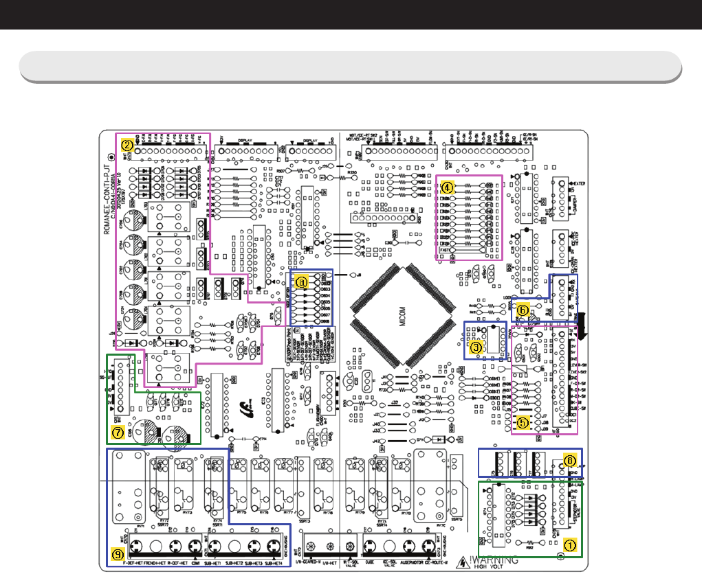
5. PCB DIAGRAM
5-1. PCB Layout with part positions (Main Board)
1. Step-Valve Controlling Circuit (TDM Cycle)
2. Fan Motor Driving Circuit : It supplies to various types of motors (7.0V ~ 12.0V)
3. EEPROM : It stores various types of data.
4. By receiving various sensor signals, it sends them to MICOM after removing noise.
5. PBA Panel Communication and Power Supply Circuit (& SPI2 Driving)
6. Power Line Communication Circuit (PLC Input / Output)
7. Inverter Comp Driving Signal Section
8. LED Lamp Controlling
9. AC Load Controlling (Driver IC, Relay, AC Connector)
a. Diode Option Setting Section
This document cannot be used without Samsung's authorization
Contents Summary of Samsung Rf32Fm
- Page 1REFRIGERATOR FRENCH DOOR REFRIGERATOR MODEL NAME: RF32FM** MODEL CODE: RF32FMQDBSR/AA REFRIGERATOR CONTENTS 1. Precautions (Safety Warnings) .........5 2. Product Features and Specifications ...9 3. Disassembly and Reassembly ....... 17 4. Troubleshooting .......................... 41 5. PCB Diagram
- Page 2WARNING IMPORTANT SAFETY NOTICE The service guide is for service technicians with sufficient background in electrical, electronic and mechanical engineering. Any attempt to repair the appliance yourself may result in personal injury and property damage. The manufacturer or dealer will not be held re
- Page 3CONTENTS 1. Precautions (Safety Warnings) ...................................................................5 2. Product Features and Specifications ..........................................................9 2-1. Compartment Features by Model .......................................................
- Page 4CONTENTS 4-2. Troubleshooting by symptom ..................................................................................................................... 58 4-2-1. When there is no power at Inverter PCB (F Room Inverter, LC3-3A) ...................................... 58 4-2-2. When the F Room C
- Page 51. PRECAUTIONS (SAFETY WARNINGS) ● Unplug the appliance before replacing or repairing electrical parts. ⇒ Be careful to avoid electric shock. ● Always use only the correct replacement parts. ⇒ Check the model name, rating voltage, rating current, running temperature symbols. ● When troubleshooting,
- Page 6PRECAUTIONS(SAFETY WARNINGS) Read all instructions before repairing the product and follow the instructions in order to prevent danger or property damage. Plug out and remove all the items in regrigerator prior to repair. CAUTION/WARNING SYMBOLS DISPLAYED SYMBOLS means "Prohibited". Indicates that a
- Page 7PRECAUTIONS(SAFETY WARNINGS) ❈ Please let users know following warnings & cautions in detail. Warning & Caution Customers should not store glass Customers should not store narrow Drugs requiring precise bottles of liquid in the freezer section. or long bottles or food in a small temperatures should
- Page 8PRECAUTIONS(SAFETY WARNINGS) FLOORING For proper installation, this refrigerator must be placed on a level surface of hard material that is the same height as the rest of the flooring. This surface should be strong enough to support a fully loaded refrigerator, or approximately 660 lb (299kg). MOVIN
- Page 92. PRODUCT FEATURES AND SPECIFICATIONS 2-1. Compartment Features by Model Water Dispenser model : RF32FM** Fridge Freezer Cool Select Room Appearance Fridge Compartment Freezer Compartment / Cool Select Room A) Handle 1) Refrigerator lamps 7) Freezer lamps B) Buttons / Indicators 2) Refrigerator she
- Page 10PRODUCT FEATURES AND SPECIFICATIONS 2-2. Basic Product Specifications (inch/mm) Item Specifications Model no. RF32FM** External dimensions (width x depth x 35 ¾” X 35 ¾” X 72 7/8” , (908 X 908 X 1850) height) Packing dimensions (width x depth x 38 1/4" X 38 1/4" X 79 1/2" (972 X 972 X 2003) height)
- Page 11PRODUCT FEATURES AND SPECIFICATIONS 2-3. Comparison of Specifications (inch, mm) No. Module RF32FM** 1 Dimensions 35 ¾” X 35 ¾” X 72 7/8” , (908 X 908 X 1850) 2 Door SWING 4 Door/ STS Fridge Top: 6 high-luminance lamps/ Side: 3 lamps*2ea 3 Lighting Freezer/ 1 high-luminance lamp (top of compartment)
- Page 12PRODUCT FEATURES AND SPECIFICATIONS 2-4. Specifications Item Dimensions Model RF32FM** Freezer performance (4 stars) ● It will apply to product from June in 2014 Freezer MSV172AL1B/E01 Model no. MSV172AL1B/E01 Compressor Fridge MSV460AM1B/E01 NC1MV43AMP/E01 Driving type INVERTER Freezer Split Fin Ty
- Page 13PRODUCT FEATURES AND SPECIFICATIONS 2-5. Dimensions 35 ¾” (908 mm) 49 ½” (1256 mm) 30 15 16” 35 ¾” (785 mm) (908 mm) 19 ¾” (502 mm) 4 ⅜" (112mm) 59 ¾” (1517 mm) (The model manufactured before Feb. 26 , 2013 is 1450mm.) 35 ¾” (908 mm) 71 ¾” 72 ⅞” (1822 mm) (1850 mm) 13
- Page 14PRODUCT FEATURES AND SPECIFICATIONS 2-6. ICE-MAKER Function - The ICE-MAKER function is an option and the following explains the function of these models. - The ICE-MAKER is a kit that supplies water on its own, freezes water into ice and stores the ice cubes in the Ice Container with the capability
- Page 15PRODUCT FEATURES AND SPECIFICATIONS 3) General Operation • Water Supply > Stand-by Time for Ice Making > Temperature Checking for Ice Maker Sensor > Ice Removing Water Supply Ice Making Ice Removing 1. After supplying water, it stands by for 14 minutes before starting the ice making. After that, it
- Page 16PRODUCT FEATURES AND SPECIFICATIONS 2-7. Material Specification Photograph Part Name Part Code AMOUNT FILTER WATER-ASSY DA29-00019A 1 CASE LAMP REF DA97-12606A 1 LED LAMP SIDE DA41-00519Q 2 LED LAMP CONV (FRE) DA41-00676G 6(1set) Front Rear 16
- Page 173. DISASSEMBLY AND REASSEMBLY 3-1. Precautions • Before replacing or repairing an electrical part, be sure to unplug the product's power cord. - Failing to do so may result in electric shock. • Be sure to replace any electrical parts with rated parts. - Be sure to check the model no, rated power vol
- Page 18DISASSEMBLY AND REASSEMBLY 3-2. Refrigerator Door How To Do Descriptive Picture 1. Remove the 3 screws fixing the Top Table and separate the Top Table (①). 2. Separate the 2 housing connectors (②) from the hinge at the top left of the fridge compartment door and the 1 housing connector (②-1) from th
- Page 19DISASSEMBLY AND REASSEMBLY 3-3. Disassembling the Freezer There is a heater wire at the bottom of the freezer compartment. Before disassembling the door, be sure to disassemble the heater housing! Caution How To Do Descriptive Picture 1. Open the freezer compartment door and remove the screw fixing
- Page 20DISASSEMBLY AND REASSEMBLY 3-4. Disassembling the Middle Hinge How To Do Descriptive Picture 1. Remove the 2 screws (③, ④) with a (+) screw driver and remove the 2 bolts (①, ②) with a 4.95mm hexagonal wrench to separate the middle hinge. When reassembling the hinge, be sure to fix it in the followin
- Page 21DISASSEMBLY AND REASSEMBLY 3-6. Disassembling the Reed Switch How To Do Descriptive Picture 1. Open the freezer/Cool Select Room door and check the location of the upper reed switch. 2. Insert the (-) screw driver into the groove next to the arrow to separate the Switch Cover. Applying excessive for
- Page 22DISASSEMBLY AND REASSEMBLY 3-7. Disassembling the Display How To Do Descriptive Picture 1. Remove the screw (1ea) on the bottom of the Dispenser. 2. Hold the bottom of the Dispenser and pull it forward to take it off from its locking tabs. And, remove the assembly by pulling it down. 3. Separate the
- Page 23DISASSEMBLY AND REASSEMBLY 3-8. Disassembling the Main PCB and Inverter PCB How To Do Descriptive Picture 1. Pull the refrigerator forward to secure sufficient work space behind the refrigerator. 2. Remove the 3 screws. 3. Separate the 19 housing connectors. (However, the number of housing connector
- Page 24DISASSEMBLY AND REASSEMBLY 3-9. Dispenser How To Do Descriptive Picture 1. .With a flat-head (-) screwdriver, separate the Wire Connector. 2. Remove the two screws from the Case Ice Route Assy. 3. Pull out the Case Ice Route Assy. 24
- Page 25DISASSEMBLY AND REASSEMBLY How To Do Descriptive Picture 4. Do the assembly in the reverse order of the disassembly. When assembling the Case-Ice Route Assy, assemble the Water Hose properly. 5. When assembling the Display, slide it up and tap on the bottom of it slightly to complete the assembly. 2
- Page 26DISASSEMBLY AND REASSEMBLY 3-10. Case Water Filter How To Do Descriptive Picture To disassemble the Case Water Filter, remove the water filter and all drawers and shelves. 1. Disconnect the 2 housing connectors. 2. Pull out the water hose(blue) from the tube fitting by pushing in on the locking ring
- Page 27DISASSEMBLY AND REASSEMBLY 3-11. Water Filter (Assembly & Disassembly) How To Do Descriptive Picture 1. Turn the water filter count-clockwise. (Refer to the picture) 2. Remove the water filter by pulling it. (Refer to the picture) 3. Push the water filter directly. 4. Turn the water filter clockwise
- Page 28DISASSEMBLY AND REASSEMBLY 3-12. Disassembling the REF EVAP Cover How To Do Descriptive Picture 1. Remove the screw cover with the (-) screw driver. (See the figure) Take care not to scratch the cabinet or damage the screw cover. Caution 2. Remove the 4 screws. 3. Pull the centre angle forward and p
- Page 29DISASSEMBLY AND REASSEMBLY 3-13. Disassembling the FRE EVAP Cover How To Do Descriptive Picture 1. Remove all the shelves and drawers. 2. Remove the 2 screws from both sides of the EVAP Cover. 3. Separate the EVAP Cover by pulling the bottom part forward. 4. Separate the housing connector from the m
- Page 30DISASSEMBLY AND REASSEMBLY 3-14. Disassembling the Machine Compartment Motor Fan How To Do Descriptive Picture 1. Remove the 6 screws from the COMP Cover. 2. Separate the housing connector. 3. Remove the screw from the bottom part of the Motor Support Circuit Assy and pull the assy forward to separa
- Page 31DISASSEMBLY AND REASSEMBLY 3-15. Disassembling the Relay Protector O/L How To Do Descriptive Picture 1. Remove the 6 screws from the COMP Cover. 2. Separate the Relay Cover with the (-) screw driver. When separating the cover, the pipe may fold and if excessive force is Caution applied, a hand may b
- Page 32DISASSEMBLY AND REASSEMBLY 3-16. Disassembling the Step Valve How To Do Descriptive Picture 1. Remove the 6 screws from the COMP Cover. 2. Remove the screw and pull the Step Valve forward to separate it. 3. Separate the housing connector from the Step Valve. 4. Remove the refrigerant and then separa
- Page 33DISASSEMBLY AND REASSEMBLY 3-17. Disassembling the Fridge Internal Lamp How To Do Descriptive Picture 1. Insert the (-) screw driver into the hook at the back and pull the internal lamp cover forward to separate it. Take care not to scratch the cabinet or damage the screw cover. Caution Be sure to u
- Page 34DISASSEMBLY AND REASSEMBLY 3-19. Disassembling the Tempered Glass Shelf How To Do Descriptive Picture 1. Lift the shelf up slightly and pull it forward to separate it. 3-20. Folder Shelf Assembling How To Do Descriptive Picture 1. Remove each one of the screws (2ea in total) from the front and the b
- Page 35DISASSEMBLY AND REASSEMBLY 3-21. Disassembling the Vegetable Shelf How To Do Descriptive Picture 1. Remove the guard in front of the vegetable drawers and then remove the vegetable drawers as shown by the figure. 2. Lift the vegetable shelf (②) while pressing both sides of the Snap Fit (①). (Refer t
- Page 36DISASSEMBLY AND REASSEMBLY 3-22. Disassembling the French How To Do Descriptive Picture 1. Remove the 2 screws. 2. Lift the French upward perpendicularly to separate it. (Refer to the figure) 3. Separate the housing connector inside the French. Note The French here refers to the part that looks like
- Page 37DISASSEMBLY AND REASSEMBLY 3-23. Disassembling the Freezer / Cool Select Room Evaporator How To Do Descriptive Picture 1. Remove all the shelves and drawers and remove the 2 screws on each of the left and right sides of the EVAP Cover. 2. Pull the bottom part of the EVAP Cover forward to separate it
- Page 38DISASSEMBLY AND REASSEMBLY 3-24. Ice-Maker How To Do Descriptive Picture 1. Wait for 5 minutes after manual defrost of freezer and fresh food compartments. (Reference of Forced Defrost method in troubleshooting) Button 2. While pressing the tab on the top right side, lift up the Ice Bucket and pull
- Page 39DISASSEMBLY AND REASSEMBLY How To Do Descriptive Picture 6. Remove the screw from the Duct Tray-ice. 7. With a flat blade screwdriver, push the duct to the right and remove it from the locking tab. (Refer to the image.) 8. With a flat blade screwdriver, pry down on the refrigerant tube to separate i
- Page 40DISASSEMBLY AND REASSEMBLY 3-25. Auger Motor Fan How To Do Descriptive Picture 1. Disconnect the FAN-AUGER-ASSY Connector. 2. Hold the Hook on the bottom of the FAN-AUGER- ASSY and lift it up to make it free from the Locking Tab. 3. While lifting it up, take the FAN-AUGER-ASSY out of the Ice Maker C
- Page 414. TROUBLESHOOTING 4-1. Functions for failure diagnosis 4-1-1. Test mode (manual operating / manual defrosting function) • If CoolSelect+ Key + Fridge Key on the front of panel are pressed simultaneously for 8 seconds , it will be chang to the test mode and all displays on the front of panel will be
- Page 42TROUBLESHOOTING 2) Forced Operating function 2-1) If you press the Lock key once in Test Mode, the Display shows "FF" indicating a Forced Operation. At this time, the buzzer sounds a beep to indicate a Forced Operation. 2-2) In the Forced Operation (FF), if you press the Lock key again, "OF c" is di
- Page 43TROUBLESHOOTING 3) Forced defrosting function 3-1) If you press the Lock key again while the Forced Operation (Fr) is running, Fd is displayed on the Display, the Forced Operation (Fr) is cancelled immediately and the Forced defrosting (Fd) operation runs. 3-2) If Forced Freezing, Cool Select defros
- Page 44TROUBLESHOOTING 4-1-3. Self-diagnostic function 1) Self-diagnostic function in the Initial power ON 1-1) Micom operates self-diagnostic function to check the temperature sensor condition within 1 second when the refrigerator turned On initially. 1-2) If bad sensor is detected by the self-diagnostic
- Page 45TROUBLESHOOTING ✽ Detailed information about self-diagnostic error codes ※ For sensors (no. 1~7), refer to the sensor check points of the Main PCB Error Code Part Display Criteria To check if the part is normal The voltage between the Main PCB CN30 pins 1 Freezer Sensor and 3 should be within the 4.
- Page 46TROUBLESHOOTING Error Code Part Display Criteria To check if the part is normal After separating the MAIN PCB CN70 wire from the PCB, check the resistance between CN70 7 and Freezer Defrosting The separation of the freezer 1. (For the resistance value, refer to the electric Error compartment defrost
- Page 47TROUBLESHOOTING Error Code Part Display Criteria To check if the part is normal When the freezer temperature is abnormally The temperature has been abnormally increased. Check The F compartment high or the freezer door is open for a if the door has been open for a long time or if hot food abnormal h
- Page 48TROUBLESHOOTING Error Code Part Display Criteria To check if the part is normal This error code is displayed when an Check the compressor wire connections. Check the R Comp location abnormal current is detected in the soldering status of the inverter PCB. (Check if any parts detection error compress
- Page 49TROUBLESHOOTING 4-1-4. Display function of Load condition ① ① ② ① If CoolSelect+ Key + Energy Saver are pressed simultaneously for 6 seconds, ALL ON/OFF will blink with 0.5interval for 2 seconds. ② If take the finger off from above keys and press Fridge, load condition mode will be started. 1) If Po
- Page 50TROUBLESHOOTING ✽ Load mode checklist No. Part Display (LED) Description "a" and "b" at the lowest order digit of the In the case of the R-FAN HIGHEST operation, the 1 R-FAN HIGHEST R compartment corresponding LED is turned on. "a" at the lowest order digit of the R In the case of the R-FAN HIGH ope
- Page 51TROUBLESHOOTING 4-1-5. Cooling Off Mode setting function ① ① ① If CoolSelect+ Key + Freezer Key are pressed for 5 seconds, Cooling Off Mode will be started. 1) If CoolSelect+ Key + Freezer are pressed simultaneously for 5 seconds during normal operation, Cooling Off Mode will be started with buzzer
- Page 52TROUBLESHOOTING KEY control method after converting to option mode ※ R Key control in option mode CoolSelect+ Key Code Down key Freezer Key Code Up key Energy Saver Reference Value down key Fridge key Reference Value Up key • If the display changes to option setting mode, all displays will be off ex
- Page 53TROUBLESHOOTING Code Reference Value 1) For example, if you want to change freezer compartment standard temperature to -2°C(-4℉) by operating option, do as below. This function is for changing the standard temperature. In -19°C(-2℉) of current temperature of freezer compartment, if you make the temp
- Page 54TROUBLESHOOTING 4-1-7. Option TABLE 1) Temperature changing table of freezer compartment Set item Freezer Temp Shift MODEL RF32FM** Reference Fridge Room 7-SEG Value 0 Setting value FZ Temp. compartment Code compensation 0 0.0℃(0℉) 1 -0.5℃(-1℉) 2 -1.0℃(-2℉) 3 -1.5℃(-3℉) 4 -2.0℃(-4℉) 5 -2.5℃(-5℉) 6 -
- Page 55TROUBLESHOOTING 3) Cool Select Room Temperature Change Table Setting Item CV Compartment Temperature Offset Model Common for all models Location: R compartment temperature display Option 3 F compartment temperature Temp. display setting compensation 0 0.0 ℃ (0 ℉) 1 -0.5 ℃ (-1 ℉) 2 -1.0 ℃ (-2 ℉) 3 -1
- Page 56TROUBLESHOOTING 5) Amount of water supply to ice tray Set item Amount of Water Supply Reference Fridge Room 7-SEG Value 32 Setting value FZ compartment Amount of water Code supply 0 110CC 1 120CC 2 - 3 - 4 - 5 - 6 - Code Reference Value 7 - ex) If you want to change the amount of water supply to ice
- Page 57TROUBLESHOOTING 7) Temperature changing table of ice room Set item Ice Room Temp Shift Reference Fridge Room 7-SEG Value 34 Setting value FZ Temp. compartment compensation Code 0 0 ℉(0.0 ℃) 1 -1 ℉(-0.5 ℃) 2 -2 ℉(-1.0 ℃) 3 -3 ℉(-1.5 ℃) 4 -4 ℉(-2.0 ℃) 5 -5 ℉(-2.5 ℃) 6 -6 ℉(-3.0 ℃) 7 -7 ℉(-3.5 ℃) 8 +1
- Page 58This document cannot be used without Samsung's authorization TROUBLESHOOTING 4-2. Troubleshooting by symptom 4-2-1. When there is no power at Inverter PCB (F Room Inverter, LC3-3A) Caution AC120V and DC170V flow Start - To check the Inverter PCB, refer to the 'Operations' and on the Inverter PCB Pow
- Page 59This document cannot be used without Samsung's authorization TROUBLESHOOTING 4-2-2. When the F Room Compressor(ENV2) is not operating (F Room Inverter, LC3-3A) When the inverter PCB LED Start is ON, it indicates that the compressor is operating normally No 10 minutes have passed since the COMP was t
- Page 60This document cannot be used without Samsung's authorization TROUBLESHOOTING SPM FREEWHEELING DIODE VOLTAGE VALUE (F Room Inverter LC3-3A) VBS : High-side Control Bias Voltage VBSD: Bootstrap Diode Voltage VCC(HS): High-side Supply Voltage VCC(LS): Low-side Supply Voltage FWD: Free Wheeling Diode IG
- Page 61This document cannot be used without Samsung's authorization TROUBLESHOOTING 4-2-3. When the R Room Compressor (MSV) does not operate (R Room Inverter, LC4) When the inverter PCB LED Start is ON, it indicates that the compressor is operating normally No 10 minutes have passed since the COMP was turn
- Page 62This document cannot be used without Samsung's authorization TROUBLESHOOTING The SPM FREEWHEELING DIODE VOLTAGE VALUE (R Room Inverter LC4 ) 62
- Page 63This document cannot be used without Samsung's authorization TROUBLESHOOTING 4-2-4. The LED blinking frequency depending on the protection functions (F/R Room Inverter PCB) If the Failure Condition is detected while the compressor is operating, stop the Compressor operating immediately and wait for
- Page 64This document cannot be used without Samsung's authorization TROUBLESHOOTING 4-2-5. When a "1E", "2E", "4E", "5E", "6E", "7E", "13E", "16E", "24E" or "25E" error occurs (defrosting failure) Start Are the F and R defrosting sensors normal when they are checked by the self diagnostic function? No Yes
- Page 65TROUBLESHOOTING 4-2-6. When occur the cooling defect by a lot of frosting on the Fridge compartment Start (Cooling defect in the Fridge compartment) Dose the compressor of the fridge compartment operate properly? Fix the compressor operation defect No Yes Is there any refrigerant leakage of fridge c
- Page 66This document cannot be used without Samsung's authorization TROUBLESHOOTING 4-2-7. When an error occurs in self diagnostic mode (in case of a sensor error) - A sensor error is displayed on the front display panel of the refrigerator. If a sensor error is detected when the power is supplied to the r
- Page 67TROUBLESHOOTING 4-2-8. When the Fan does now operate (F, R, M, C - FAN) - This refrigerator uses the BLDC Fan Motor. The BLDC Motor operates with DC 7~12V. - Under Comp On conditions, the R-Fan operates generally. But, when the ambient temperature is high or when you open and close the Door once, it
- Page 68TROUBLESHOOTING 4-2-9. When the Fan does now operate (ICE ROOM - FAN) - This refrigerator uses the BLDC Fan Motor. The BLDC Motor operates with DC 7~12V. - Under Comp On conditions, the R-Fan operates generally. - When there is defect, turn on the Self-Diagnosis function and confirm the defect befor
- Page 69TROUBLESHOOTING 4-2-10. When the ICE MAKER does not operate 1. Water supplies to the Ice Maker automatically and ice is to be scooped out depending on its temperature and the timing. 2. Power is always applied to the Ice Maker. So, refer to the disassembly section to remove it. 3. To check the opera
- Page 70TROUBLESHOOTING 4-2-11. When water does not supply at Ice Maker Advance Checking 1. Water is directly supplied to the Water Valve. So, make sure to cut off the water before doing repairs. 2. There is electricity flowing in the wire. So, take extra care not to get electric shock. Start Is the Valve o
- Page 71TROUBLESHOOTING 4-2-12. When Cubed or Crushed ice does not dispense properly The operation condition is that Start the Fridge Door is closed. No It dispenses ice? Yes No It dispenses ice? Yes No Ice Off is selected off? ① Check Ice Eject S/W ② Check DOOR S/W(Including Auger Safety Switch) ③ Check Ic
- Page 72TROUBLESHOOTING 4-2-13. When COVER ICE ROUTE MOTOR (GEARED MOTOR) does not work properly Caution 1. When replacing the Cover Ice Motor, pull out the plug to avoid an electric shock. 2. Be careful! When disassemble the Cover Ice Motor, spring can jumped out and may cause personal injury. 3. Motor wil
- Page 73This document cannot be used without Samsung's authorization TROUBLESHOOTING 4-2-14. When the alarm is heard continuously (buzzer sound) ① If a ‘dingdong' sound is heard continuously or the ‘Refrigerator door Start is opened’ message is displayed. The door is slightly open. Is the door open slightly
- Page 74This document cannot be used without Samsung's authorization TROUBLESHOOTING ③ When there is no buzzer sound. The buzzer is attached to the Panel PBA in this model. If the buzzer does not sound when you press a key, run the Forced Operating operation or open the door, separate the Panel PBA and chec
- Page 75This document cannot be used without Samsung's authorization TROUBLESHOOTING 4-2-15. When the Panel PBA does not work properly ※ If no key is pressed for 10 seconds, the LEDs ① When the Panel PBA is not turned on or only some of the lamps are of the display are turned off. When the display turned on
- Page 76This document cannot be used without Samsung's authorization TROUBLESHOOTING 4-2-16. When the internal lamp of the freezer or fridge is not turned on Note. 1. If the freezer door is opened, the door switch is open-circuited and 5V is input to the micom indicating that the door is open. Then, if 5V i
- Page 77This document cannot be used without Samsung's authorization TROUBLESHOOTING ■ Voltage and resistance of the temperature sensor by temperature Temp. Temp. Resistance Voltage Temp. Temp. Resistance Voltage Temp. Temp. Resistance Voltage (℉) (℃) (㏀) (V) (℉) (℃) (㏀) (V) (℉) (℃) (㏀) (V) -43.6 -42 98.9 4
- Page 78This document cannot be used without Samsung's authorization TROUBLESHOOTING ■ Voltage of the humidity sensor by humidity RH (%) Output (mV) RH (%) Output (mV) 0 909 51 2376 1 943 52 2402 2 977 53 2428 3 1010 54 2454 4 1043 55 2480 5 1076 56 2505 6 1109 57 2530 7 1141 58 2555 8 1173 59 2580 9 1205 6
- Page 79This document cannot be used without Samsung's authorization 5. PCB DIAGRAM 5-1. PCB Layout with part positions (Main Board) 1. Step-Valve Controlling Circuit (TDM Cycle) 2. Fan Motor Driving Circuit : It supplies to various types of motors (7.0V ~ 12.0V) 3. EEPROM : It stores various types of data.
- Page 80This document cannot be used without Samsung's authorization PCB DIAGRAM 5-2. PCB Layout with part positions (F Room Inverter, LC3-3A) ③ ① ⑦ ② ④ ⑥ ⑤ 1. PCB Power Supply: From the SMPS circuit, it supplies 15V and 5V for the Main PBA control and supplies 15V and 5V to the Inverter circuit for the Com
- Page 81This document cannot be used without Samsung's authorization PCB DIAGRAM 5-3. PCB Layout with part positions (R Room Inverter, LC4) 1. PCB Power Supply: Supplies DC 15V and 5V to the Inverter circuit for the Compressor control. 2. Inverter Control Circuit: Fridge Compressor Control Circuit. 3. COMP
- Page 82This document cannot be used without Samsung's authorization PCB DIAGRAM 5-4. Connector Layout with part positions (Main Board) 82
- Page 83This document cannot be used without Samsung's authorization PCB DIAGRAM 5-5. Connector Layout with part positions (F Room Inverter, LC3-3A) Phase Phase Phase 83
- Page 84This document cannot be used without Samsung's authorization PCB DIAGRAM 5-6. Connector Layout with part positions (R Room Inverter, LC4) AC Power (AC 110V) U Pharse V Pharse W Pharse 84
- Page 85This document cannot be used without Samsung's authorization 6. WIRING DIAGRAM 6-1. Basic Model 85
- Page 86This document cannot be used without Samsung's authorization 7. BLOCK DIAGRAM 7-1. Basic Model 86
- Page 87This document cannot be used without Samsung's authorization BLOCK DIAGRAM 7-2. Whole block diagram (F Room Inverter, LC3-3A) 87
- Page 88This document cannot be used without Samsung's authorization BLOCK DIAGRAM 7-3. Whole block diagram (R Room Inverter, LC4) 88
- Page 898. REFERENCES 8-1. Glossary About Inverter technology This is a technology for ensuring efficiency that automatically controls the freezing and cooling performance depending on the various conditions including the surrounding temperature, the number of times the door is opened and the amount of stor
- Page 90REFERENCES ✽ Glossary Terminology Description LED stands for Light Emitting Diode. LED An LED is a semiconductor device that emits visible light when an electric current passes through it. This refers to the communication ports of the micom. Tx, Rx TX : Transmit signal. RX : Receive Signal. The IC u
- Page 91REFERENCES 8-2. French Heater Control Using a Humidity Sensor ▶ The French heater of the fridge is controlled by the humidity sensor value, the surrounding temperature and the fridge temperature. ▶ If the output voltage of the humidity sensor is 0.6V or lower or 4.7V or higher, it is judged to be a
- Page 92REFERENCES 8-3. Model Numbering Convention 92
- Page 93REFERENCES 8-4. Troubleshooting. Check the following before calling the service centre Symptom Troubleshooting - The sound may be heard when the refrigerant inside the refrigerator flows as a gas and a liquid. A liquid flowing sound is heard! - In addition, the frost attached to the cooler may gener
- Page 94REFERENCES Symptom Troubleshooting - Since the lamp in the freezer generates heat if the door is open for a long time, frost The main body of the refrigerator and may appear due to the temperature difference between the external air and the freezer the internal lamp cover in the freezer compartment.
- Page 95272, Oseon-Dong, Gwangsan-Gu, Gwangju-City, Korea, 506-253 TEL: 82-62-950-6193, 6896 FAX: 82-62-950-6829 Europe, CIS, Mideast & Africa: gspn1.samsungcsportal.com Asia: gspn2.samsungcsportal.com North & Latin America: gspn3.samsungcsportal.com China: china.samsungportal.com - This Service Manual is t