The temperature in a commercial refrigeration unit is regulated by the low-pressure control.
The low-pressure control intersects the wire going into either the run or common terminal of the compressor. There is a switch inside the control operated by a diaphragm. This diaphragm is connected to the suction line by a length of small-diameter tubing (the sensing bulb) through the low-pressure access valve. The pressure changes in the suction line are transmitted to the diaphragm through this line. Some of these valves have a Y-adapter so that both this sensing bulb and a gauge manifold can be connected. When the pressure inside the suction line falls below a preset point, it causes the diaphragm to flex, turning off the electrical switch and disrupting power to the compressor.
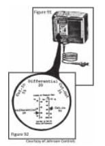
Figures 91 and 92 show a low-pressure motor control. This is a spring-loaded device, which is sensitive to the suction-line pressure. As the compressor runs, the temperature and pressure in the evaporator are lowered. As soon as pressure drops to a given point, it cuts off power to the compressor. When the pressure in the evaporator rises to a predetermined setting, the control reconnects power to the compressor, the compressor resumes running, and the cycle is repeated. This control device is often used in drinking fountains and other units where a constant temperature is needed.

Until the pressure in the suction line gets high enough to flex the diaphragm, the unit remains in the off cycle.
NOTE: It is normal for a refrigeration unit to fail to start after opening the sealed system. The low-pressure control reacts to the abnormal pressures (created by opening the system) by having the bellows within the control keep the circuit to the compressor open. It can be restarted by manual operation of the tripping switch. Lift the bellows tab with the blade of a screwdriver (at arrow in fig. 93) for a few seconds (time depends on the size of the unit). DO NOT operate the control at any other point or it will be damaged.
There are two adjusting screws on top of the control. One for the cut-in adjustment, and one for the cut-out. As the adjustment screws are turned, an indicator moves up or down a scale calibrated in pounds. (See fig. 93) Cut-in refers to the pressure at which the compressor resumes operating. (Not warmer than that point.) And cut-out refers to pressure at which the compressor stops operating. (Not colder than that point.)
NOTE: After replacing the low-pressure control, check the pressures in the unit if it is suspected that any refrigerant has escaped. Watch it cycle two or three times after restarting it. Remember that pressure controls are affected by the pressures in the sealed system and not by the temperature. Use the chart on page 124 to convert any temperature to its corresponding pressure. To calculate cut-in and cut-out, do the following:
1. Using the chart on page 133, determine the evaporator pressure for the warmest allowable temperature. Then turn the cut-in screw until the needle indicates the correct pressure.
2. Determine the lowest allowable evaporator temperature. (Assume a 20°F drop in evaporator temperature is allowable.)
3. Find the corresponding pressure for the allowable temperature drop for the refrigerant used in the unit.
4. Deduct the allowable pressure drop from the cut-in pressure and the result will be the differential adjustment.
5. Turn the differential adjustment screw until the indicator is at the proper setting. When the pressure in the evaporator drops to the lowest allowable point, the cut-out switch will automatically turn off the compressor until the low-side pressure rises to its preset cut-in pressure range.
EXAMPLE: The desired temperature of a walk-in cooler using R-12 is about 35°F. Determine the cut-in and differential adjustments on the low-pressure control.
1. The corresponding pressure for R-12 at 35°F (on page 133, The Temperature-Pressure Chart) is 32.6 psi. This will be the cut-in setting.
2. Since the temperature of the evaporator should always be kept 20°F below the desired refrigerated ambient temperature, to determine the cut-out setting on the low-pressure control: 35°F – 20°F = 15°F.
3. Refer to the temperature-pressure chart to find the corresponding pressure at 15°F for R-12. Convert the 15°F to pressure, which will be 17.7 psi. According to step 4 above, 32.6 – 17.7 = 14.9 psi will be the differential adjustment. By setting the differential adjustment, the pressure control will cut in at 35°F and cut out at 15°F.
4. Using a screwdriver, turn the cut-in screw until the cut-in needle indicates 32.6 psi.
5. Turn the cut-out screw until the cut-out needle indicates 14.9 psi. Now the walk-in cooler temperature is set to be kept at about 35°F. The pressure control will cut in at 35°F and cut out at 15°F.