A solenoid valve is an electromechanical device, which operates by creating and eliminating a magnetic field. It is primarily composed of a coil of wire (windings) and an armature (metal rod or plunger). When the circuit is closed, the coil creates a magnetic field which causes the metal rod to move upward its valve seat. The seat, when free of its obstruction, allows refrigerant to flow through it. When the electrical circuit is opened, the magnetic field disperses and the plunger falls back into its seat. This type of valve is known as a direct-acting solenoid valve.

Pilot-operated solenoid valves use a combination of the solenoid coil and the line pressure to operate. In this type of valve, the plunger is attached to a needle valve covering a pilot orifice rather than the main port. The line pressure holds an independent piston or diaphragm closed against the main port. (See fig. 98b.)

When the coil is energized, the plunger is pulled into the center of the coil, opening the pilot orifice. Once the pilot port is opened, the line pressure above the diaphragm is allowed to bleed off to the low side or outlet of the valve, thus, relieving the pressure on the top of the diaphragm. The inlet pressure then pushes the diaphragm up and off the main valve port and holds it there, allowing full flow of the fluid. When the coil is de-energized, the plunger drops and closes the pilot orifice. Pressure begins to build up above the diaphragm by means of a bleed hole in the piston diaphragm until it, plus the weight of the diaphragm and spring, cause it to close on the main valve port. This type of solenoid valve requires a minimum pressure difference between inlet and outlet in order to operate.
The manual stem as shown in figure 98b is used to manually open the valve if the line current is not available or for flushing in cleanup or other service maintenance functions.
The two-way valve, which is the most common type of solenoid valve, controls fluid flow in one line. It has an inlet and an outlet connection. This valve can be of the direct-acting or pilot-operated type, depending on the need. When the coil is de-energized, the two-way valve is normally closed. Although normally closed is the most widely used, two-way valves are manufactured to be normally open when the coil is de-energized. See figure 98c for an example of a two-way valve.
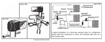
The three-way valve has a connection, which is common to either of two different outlets and controls refrigerant flow in two different lines. They are used chiefly in commercial refrigeration units for heat-reclaiming applications, hot gas defrost, and discharge-gas unloading applications. See figure 98d for an example of a three-way valve.
The three-way valve has its common inlet attached to the compressor discharge line. The other two outlets connect to the normal condenser and the auxiliary condenser as shown in figure 98e.
When the solenoid coil is de-energized, the pilot line to the suction side of the compressor is closed. Discharge gas pressure escapes through the bleed port into the top of the piston and drives it downward, closing the bottom seat. This allows discharge gas to flow to the normal or outside condenser.
Energizing the solenoid opens the pilot line to the suction side of the compressor and permits the discharge gas pressure on top of the piston to escape to the suction line. The discharge gas pressure below the piston now causes the piston to be driven upward, closing the outlet to the condenser and diverting the discharge gas to the auxiliary condenser. Some valves are available with an internal bleed, which drains the reclaim oil during normal operation.
This type of three-way solenoid valve is designed to meet the requirements of high temperatures and pressures existing in compressor discharge gas applications. It is specifically designed for discharge gas diverting in compressor unloading. Valves for compressor-unloading applications are usually designed to provide mounting directly on the compressor head. In this application, the valve is used for suction line use and is shown in a schematic diagram in figures 98h and 98i.
When the solenoid is de-energized, the pilot line to the suction side of the compressor is closed. This allows the suction gas to flow in the normal direction to the compressor as shown in figure 98g. When the solenoid is energized, the pilot port is opened. This enables the piston to be driven upward, closing off the suction line connection and permitting a reverse flow of the hot gas through the suction line to the evaporator for hot gas defrost.

Four-way solenoid valves ( often called reversing valves) are used almost exclusively on reverse-cycle heat pumps to select either the heating or cooling mode depending upon requirements. These valves have one common inlet and three outlets. Illustration 103 is a picture of a four-way valve.
Heat pumps and reversing valves should be increasing in volume in years to come since they conserve energy. A heat pump is a central air conditioner (or window unit) with a reverse cycle for heating. In the summer, the refrigerant absorbs heat from the house and exhausts it outdoors. In winter, the cycle is reversed with the refrigerant absorbing heat from outdoors and releasing it inside the house. The following is a detail of how the reversing valve operates.

Figures 98h and i show a schematic diagram of a four-way valve on a typical reverse-cycle heat-pump system. In figure 98i, the system is on the heating cycle with discharge gas flowing through reversing valve ports D to 2, making the indoor coil the condenser. The suction gas flows from the outdoor coil (evaporator) through reversing valve ports 1 to S and back to the compressor. With the four-way solenoid pilot de-energized, the slide is positioned so as to connect ports D with A, and B with S. When the pilot is de-energized, high-pressure discharge gas builds up on top of the main slide. The area below the main slide is isolated from the high pressure by C-cup seal and exposed to low-pressure suction gas. Thus, the unbalanced force, due to the difference between discharge and suction pressures acting on the full end area of the main slide holds the slide in the down position as shown in figure 98i.
When the coil is energized (see fig. 98h), the slide in the pilot solenoid valve raises, now connecting ports D with B and A with S. With the pilot solenoid so positioned, the discharge pressure imposed on the top of the main slide area E flows through the pilot solenoid valve to the suction side of the system. At the C end of the main slide, high-pressure discharge gas accumulates so as to increase the pressure. An unbalanced force in an upward direction is again due to the difference between discharge and suction pressures acting on opposite ends of the main slide. This unbalanced force moves the main slide to the up position (as shown in figure 98h) and the force unbalance across the area of the main slide holds the slide in the new position.
Depending on the design requirements of the manufacturer, some reversing
valves produce the cooling cycle when they are energized, and some produce
it when they are de-energized.
When the solenoid in a reversing valve fails, the valve will hold the unit only in the cycle it takes the unit to upon being energized. Sometimes, due to an internal short in the winding, the solenoid loses the ability to pull all the way in (or sticks in mid-position), in which case the unit neither heats nor cools. In either case, the defective part must be replaced.
The capacities of solenoid valves for normal liquid or suction gas refrigerant service are given in tons of refrigeration at some nominal pressure drop and standard conditions. Manufacturers’ catalogs provide extended tables to cover nearly all operating conditions for common refrigerants. Follow the manufacturer’s sizing recommendations. Do not select a valve based on line size. Pilot-operated valves require a pressure drop to operate, and selecting an oversize valve will result in the valve failing to open. Undersized valves
result in excessive pressure drops.
The solenoid valve selected must have a MOPD (maximum operating pressure differential) rating equal to or in excess of the maximum possible differential against which the valve must open. The MOPD takes into consideration both the inlet and outlet valve pressures. If a valve has a 500 psi inlet pressure and a 250 psi outlet pressure and an MOPD rating of 300 psi, it will operate since the difference (or 500 psi -250 psi) is less than the 300 psi MOPD rating. If the pressure difference is larger than the MOPD, the valve will not open.
Consideration of the safe working pressure (SWP) required is also important for proper and safe operation. A solenoid valve should not be used for an application when the pressure is higher than the safe working pressure. Solenoid valves are designed for a given type of fluid so that the materials of construction will be compatible with that fluid. Steel or ferrous metals and aluminum are used in solenoid valves for ammonia service. Special seat materials and synthetics may be used for high-temperature or ultra-low-temperature service. Special materials are required for corrosive fluids.
Special attention to electrical characteristics is also important. Required voltage and hertz must be specified to ensure proper selection. Valves for DC service often have different internal construction than valves for AC applications, so it is important to study the manufacturer’s brochure carefully.
Solenoid valves having a spring-loaded plunger or diaphragm may be installed and operated in any position; however, the older style conventional solenoid valve with a plunger, which depends on gravity to close, must always be installed with the plunger in an upright, vertical position with the pipe horizontal. An adequate strainer or filter-drier should be installed ahead of each solenoid valve to keep scale, pipe dope, solder, and other foreign matter out of the valve. When installing a solenoid valve, be sure the arrow on the valve body points in the direction of refrigerant flow. When brazing solder-type connections, do not use a torch that is too hot and point the flame away from the valve.
Allow the valve body to cool before replacing the valve inner parts to ensure that the seat material and gaskets are not damaged by the heat. Wet rags and/or chill blocks are recommended during brazing. They are necessary to keep the valve body cool so that body warpage and close coupled valves will not occur. When reassembling, do not overtorque.