Lg Ga B409U Page 4
Workshop Manuals
After the refrigerant (R600a) is completely discharged, repair any defective
parts and replace the dryer. At any case you must use the LOKRING for
connecting or replacing any part in the cycle (No Fire, No Welding).
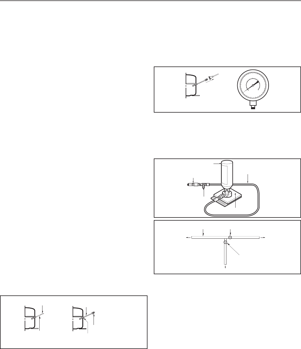
Connect the Schrader valve to pump with the coupler. And then turn the
pump on for vacuum state (Figure 3). Let the pump run until the low-
pressure gauge indicates the vacuum (gauge pressure 0, absolute
pressure -1atm or -760mmHg). Recommended vacuum time is 30 min.
Charge the N
2
gas in order to check for leakage from welding points and the
LOKRING. If leakages are found, repair the defects and repeat the vacuum
process.
After the system is completely vacuumed, fill it with the refrigerant R600a up
to what has been specified at your refrigerator Name Plate. The amount of
refrigerant (R600a) must be precisely measured within the error of ±2g by
an electron scale (Figure 4).
If you use the manifold connected with both the refrigerant (R600a)
cylinder and the vacuum pump simultaneously, make sure the
pump valve is closed (Figure 5).
Connect the charging hose (that is connected to the refrigerant (R600a)
cylinder) to the Schrader valve installed on the service tube. Then, charge
the refrigerant (R600a) by controlling the Throttle valve. When you do so,
do not fully open the Throttle valve because it may make damage to the
compressor. Gradually charge the refrigerant (R600a) by changing open
and close the Throttle Valve (5g at each time). The charging hose must use
a one-way valve to prevent the refrigerant refluence. Close the Schrader
valve cap after the refrigerant (R600a) is completely recharged.
After you completely recharge the refrigerant (R600a), perform the leakage
test by using a portable leakage detector or soapy water.
Test the low pressure (suction) parts in compressor off time and high
pressure parts in compressor on time. If the leakages are found, restart from
the refrigerant (R600a) discharging process and repairs defects of leaks.
After the leakage test, check the temperature of each parts of the cycle.
Check with hands if the CONDENSER and the case (HOT-LINE pipe) that
is contacted to the door gasket are warm. Confirm that frost is uniform
distributed on the surface of the EVAPORATOR.
SERVICING PRECAUTIONS
--4-
WEIGH SCALE
THROTTLE
VALVE
COUPLE
REFRIGERANT
(R600a)
CHARGING HOSE
FILLING OR
CHARGE TUBE
VALVE TO BE OPENED
WHEN REFILLING
VALVE TO BE CLOSED
AFTER VACUUM
TO THE VACUUM PUMP
TO THE
REFRIGERATION
SYSTEM
TO THE CHARGE
CYLINDER
TO THE
VACUUM
PUMP
PRESSURE
GAUGE
Features of refrigerant (R600a)
• Achromatic and odor less gas.
• Flammable gas and the ignition (explosion) at 494°C.
• Upper/lower explosion limit: 1.8%~8.4%/Vol.
Features of the R600a refrigerator
• Charging of 60% refrigerant compared with a R134a model
• The suction pressure is below 1bar (abs) during the operation.
• Because of its low suction pressure, the external air may flow in the
cycle system when the refrigerant leak, and it causes malfunction in
the compressor.
• The displacement of compressor using R600a must be at least
1.7 times larger than that of R134a.
• Any type of dryer is applicable (XH-5, 7, 9).
•
The EVAPORATOR or any other cycle part that has welding joint is
hidden in the foam. (If not hidden inside, the whole electric parts must be
tested with the LEAKAGE TEST according to the IEC Standard.)
• The compressor has label of the refrigerant R600a.
• Only the SVC man must have an access to the system.
Installation place
• Must be well ventilated.
• Must be 20 m
3
or larger.
• Must be no-smoking area.
• No ignitable factors must be present.
Utilities
• Refrigerant cylinder (MAX NET 300g)
• Manometer
• Vacuum pump (600l /min)
• Piercing Clamp
• Quick coupler
• Hoses (5m-1EA, 1m-3EA)
• LOKRING
• Portable Leakage detector (3g/year↓)
• Nitrogen cylinder (for leakage test)
• Concentration gauge
Make sure before Servicing
• Refrigerant
Confirm the refrigerant by checking Name Plate and the label on the
compressor, after opening the COVER ASSY, BACK-M/C.
•
If the refrigerant is R600a, you must not weld or apply a heat source.
Air Recharging in Compressor
Before refilling the refrigerant, you must perform the test according to
Chapter 5 (TROUBLESHOOTING CHART). When the defects are
found, you must discharge the residual refrigerant (R600a) in the
outdoor. For discharging the refrigerant R600a, break the narrow
portion of tube extension by hand or with a pipe cutter as shown in
Figure 1. Leave it for 30min in outside to stabilize the pressure with
ambient. Then, check the pressure by piercing the dryer part with
piercing pliers. If the refrigerant is not completely discharged, let the
refrigerator alone for more 30min in outside.
Attach the service tube installed with a Schrader valve (one-way valve)
by using the LOKRING (Figure 2). Then, connect the Schrader valve
(one-way valve) to the pump that is connected to the discharging hose
leading to the outside. When discharging the residual refrigerant, repeat
3 cycle that includes 3min of the pump running->pump off->30sec of
the compressor running.
Figure 3
Figure 4
Figure 5
POINT TO BE
BROKEN
CHARGE TUBE
EXTENSION
SCHRADER VALVE
(ONE-WAY VALVE)
LOKRING
SERVICE TUBE
EXTENSION
Figure 1 Figure 2
Contents Summary of Lg Ga B409U
- Page 1http://biz.lgservice.com REFRIGERATOR SERVICE MANUAL CAUTION BEFORE SERVICING THE UNIT, READ THE "SAFETY PRECAUTIONS" IN THIS MANUAL. MODEL: GA-B409U*QA/B379U*QA�
- Page 2
- Page 3CONTENTS SAFETY PRECAUTIONS .............................................................................................................................................. 2 SERVICING PRECAUTIONS .........................................................................................................
- Page 4SERVICING PRECAUTIONS Features of refrigerant (R600a) After the refrigerant (R600a) is completely discharged, repair any defective • Achromatic and odor less gas. parts and replace the dryer. At any case you must use the LOKRING for • Flammable gas and the ignition (explosion) at 494°C. connecting o
- Page 5SPECIFICATIONS 1.Ref. No: GA-B409U*QA ITEMS SPECIFICATIONS ITEMS SPECIFICATIONS DIMENSIONS (mm) 595(W)X651(D)X1896(H) Transparent Shelf(3 EA) NET WEIGHT (kg) 77 REFRIGERATOR Vegetable Container(1 EA) COOLING SYSTEM Fan Cooling COMPARTMENT Vegetable Container Cover(1 EA) TEMPERATURE REFRIGERATOR Knob
- Page 6PARTS IDENTIFICATION Door Swich Utility Corner (movable) Removable Rotatable Glass Shelf(2 or 3) Door Basket (3 or 5) Lamp Multi-air Flow Duct Egg Tray Tray Meat (Optional) Refrigerator Temperature Control Vegetable Drawer Handle Used to keep fruits and vegetables, etc. fresh and crisp. 2 Bottle Doo
- Page 7REPLACEMENT OF DOOR OPENING TYPE Precaution 1. Before reversing the door, first of all, you should take out food and accessories like shelves or trays which arenot fixed in the 18 fridge-freezer. 19 2. Use Torque Wrench or Spanner to fix or remove the bolt. 17 3. Do not lay the fridge-freezer down.
- Page 8DISASSEMBLY 1. DOOR 2. DOOR SWITCH • Freezer Door 1) Using the driver remove two small cap of the front. 2) Loosen four screws in upper part and disconnect top cover. 1) Loosen 2 screws and pull the Cover Lower. 3) Disconnect Lead Wire from switch. 2) Loosen hexagonal bolts fixing the lower hinge to
- Page 94 FAN AND FAN M OTOR 6 DAMPER CONT ROL 1) Remove freezer drawers. 1) Remove the Cover Lamp, R and loosen 2 screw. 2) Remove two cap, screws and loosen two screws in Grille Fan. 2) Pull the Control Box, R and separate the lead wire 3) Pull out the Grille Fan and Shroud, F. housing. 4) Disconnect the
- Page 10ADJUSTMENT 1. COMPRESSOR 3) PTC-Applied Circuit Diagram According to Starting Method for the Motor 1) Role The compressor intakes low temperature and low OVERLOAD PROTECTOR(O.L.P) pressure gas evaporated from Evaporator of the Refrigerator, and condenses this gas to high temperature C and high press
- Page 113. OLP (OVER LOAD PROTECTOR) CONTACTING 1) Definition of OLP POINT COVER (1) OLP (OVER LOAD PROTECTOR) is attached to the BIMETAL Hermetic Compressor and protects the Motor by cutting off current in Compressor Motor in case of CONTACTING over-rising temperature by Bimetal in the OLP. POINT (2) When
- Page 12TROUBLESHOOTING (Mechanical Part) 1. COMPRESSOR AND ELECTRIC COMPONENTS Power Remove the Relay Assy (Rating Voltage YES 1 Source. from the Compressor ±10%) 2 and measure the voltage between Terminal C of Compressor and Terminals M or S of Relay Assy No Voltage. 5 Applied voltage isn't Advise the cus
- Page 132. RELAY ASSY (PTC AND OLP) Normal operation of Observation value is Check another Compressor is Separate the Relay Assy 220V/50Hz : 22Ω ±30% electric impossible or poor. from Compressor and 115V/60Hz : 6.8Ω ア30% components. measure the resistance 240V/50Hz : 33Ω ±30% between M and S with a 127, 220
- Page 143. ANOTHER ELECTRIC COMPONENTS Cooling is impossible Compressor Check if current flows to doesn't run. the following Cause. components. a. Thermistor Poor contacting. b. Starting devices Shorted or broken. c. OLP Poor contacting or shorted. d. Compressor coil Coil shorted. Poor contacting Replace e.
- Page 154. SERVICE DIAGNOSIS CHART COMPL A INT POINTS TO B E CHECK ED R E M E DY Cooling is • Is the power cord unplugged from the outlet? • Plug to the outlet. impossible. • Check if the power switch is set to OFF. • Set the switch to ON. • Check if the fuse of power switch is shorted. • Replace a regular
- Page 165. REFRIGERATING CYCLE Troubleshooting Chart TEMPERATURE STATE OF STATE OF THE CAUSE OF THE REMARKS THE SET EVAPORATOR COMPRESSOR PARTIAL Freezer room and Low flowing sound of Refrigerant A little high more than • A little Refrigerant discharges. LEAKAGE Refrigerator don't cool is heard and frost fo
- Page 17General Control of Refrigerating Cycle NO. ITEMS CONTENTS AND SPECIFICATIONS REMARKS WELDING (1) H 30 • Recommend H34 containing 34% Ag in the Service ROD • Chemical Ingredients Center. Ag: 30%, Cu: 27%, Zn: 23%, Cd: 20% 1 • Brazing Temperature: 710~840°C (2) Bcup-2 • Chemical Ingredients Cu: About
- Page 18LOKRING TUBE JOINT LOKRING Figure 23. LOKRING ASSEMBLY JAWS BOLT TOOL Figure 24. LOKRING TOOL -18-�
- Page 19MICOM FUNCTION & PCB CIRCUIT EXPLAN ATION This description is made for GA-B359, B399. Please refer to overall PCB circuits for other models. 1 FUNCTION EXPOSITION 1) FUNCTION • The initial Temperature of the Freezer Compartment is -19°C respectively. You can now adjust the temperature of the compart
- Page 203) SUPER FREEZING (1) It is the function which increases the cooling speed of freezer by continuously operating compressor and freezer fan. When it’s button is pressed, GRAPHIC is on. (2) Whenever selection switch is pressed, selection/release (GRAPHIC on/off) changes in turn. (3) If power is on aft
- Page 215) DEFROSTING (1) If the accumulated time for the operation of the COMPRESSOR is meet with 7 hours, the DEFROSTING HEATER is started. (2) The first defrosting is performed at 4 hours(compressor ON) later since the power is on. (3) If DEFROST SENSOR is over 7°C during DEFROSTING, end the operation of
- Page 22O : OPERATE NORMAL OPERATION IN TROUBLE'S OCCURRING NO. ITEMS ERROR CODE LEDs DESCRIPTION COMP FAN DEFROST HEATER 1 FREEZER FREEZER SENSOR open 15 minutes On/ O O SENSOR abnormal or short. 15 minutes Off 2 DEFROST DEFROST SENSOR open O O No defrosting SENSOR abnormal or short. 3 DEFROSTING DEFROST H
- Page 232 FUNCTION DESCRIPTION 1) ELECTRIC CIRCUITS 11 VA1 14821 9 TRANS secondary side is composed of electric power circuits for RELAY driving electricity (12Vdc) and for supplying electricity to MICOM and IC (5Vdc). The voltage in each part is as follows. PARTS both ends of VA1 both ends of both ends of
- Page 244) LOAD/BUZZER OPERATION (1) LOAD OPERATION CHECK 11 9 C 7 D 5 3 E 1 COMP, KIND OF LOAD FAN MOTOR DEFROSTING HEATER COMP COOLING FAN MEASURING POINT (IC5) No.C No.D No.E ON below 1V STATE OFF 12V If the DOOR-R is opened during FAN MOTOR is operated, FAN MOTOR is stopped immediately. The A , B of DOO
- Page 255) TEMP SENSOR CIRCUITS A 7 7 28.2KF 8 8 B 28.2KF C 16.2KF The above circuit reads the surrounding temperature, DEFROSTING temperature and FREEZER ROOM temperature into MICOM(IC1). OPEN or SHORT state of each SENSOR is as follows. SENSOR CHECK POINT NORMAL (-30°C~50°C) SHORT OPEN ROOM TEMPERATURE PO
- Page 267) TEMPERATURE COMPENSATION FREEZER ROOM RESISTANCE VALUES(R1) TEMPERATURE COMPENSATION REMARKS 180 k Ω + 5. 0° C C O MP E N S A T E W A R ML Y 56 k Ω +4.0°C 33 k Ω +3.0°C 18 k Ω +2.0°C 12 k Ω +1.0°C 10 k Ω 0° C S T ANDAR D 8.2 k Ω -1.0°C 5.6 k Ω -2.0°C 3.3 k Ω -3.0°C 2 kΩ -4.0°C 470 Ω -5 . 0 ° C C
- Page 27• TEMPERATURE COMPENSATION OF FREEZER ROOM Revised resistance 470Ω 2kΩ 3.3kΩ 5.6kΩ 8.2kΩ 10kΩ 12kΩ 18kΩ 33kΩ 56kΩ 180kΩ Present resistance NOT 470Ω 1°C↑ 2°C↑ 3°C↑ 4°C↑ 5°C↑ 6°C↑ 7°C↑ 8°C↑ 9°C↑ 10°C↑ COMPENSATE NOT 2kΩ 1°C↓ 1°C↑ 2°C↑ 3°C↑ 4°C↑ 5°C↑ 6°C↑ 7°C↑ 8°C↑ 9°C↑ COMPENSATE NOT 3.3kΩ 2°C↓ 1°C↓ 1
- Page 283. SENSOR RESISTANCE CHARACTERISTICS TABLE MEASURED TEMPERATURE RESISTANCE OF FREEZER SENSOR RESISTANCE OF DEFROST SENSOR, ROOM TEMPERATURE SENSOR -2 0 ° C 2 2 . 3 kΩ 77k Ω -1 5 ° C 1 6 . 9 kΩ 60k Ω -1 0 ° C 1 3 . 0 kΩ 47.3k Ω -5 ° C 1 0 . 1 kΩ 38.4k Ω 0° C 7 . 8 kΩ 30k Ω +5 ° C 6 . 2 kΩ 24.1k Ω +1
- Page 292) REPLACEMENT PARTS LIST 06 05 04 03 02 01 W O R K D E S C R IPTION SPEC' MAKER REMARK Q TY Q TY Q TY Q TY Q TY Q TY NO. 1 1 1 1 1 1 1 PWB,MAIN FR-1(DS-1107A) SUZHONGDAZHAN t=1.6 JIANGSULING 1J 1G 1D 1D 1J 1G 2 TRANS PCB K .T .C TRANS T A E SU N G 1 1 1 1 3 JE 202-1T -05 (9P -2,4,6,8) JA E E U N /
- Page 303) P CB ASS'Y, DISPLAY AND PARTS LIST 03 02 01 WORK DESCRIPTION SPEC MAKER REARK Qty Qty Qty No. 1 1 1 1 IC KIA7042AP KEC IC2 1 1 1 2 IC FUJITSU MB89F202 FUJITSU IC1 4 4 4 3 TRANSISTOR KRA106M KEC Q2-5 1 1 1 4 TRANSISTOR KRA106M KEC Q6 3 3 3 5 CAPACITOR,METAL GLAZED 104 50V TAE YANG/YAGEO CC1-3,13 1
- Page 315. PCB assembly,MAIN circuit drawing- The PCB assembly,MAIN circuit drawing may change without notice. CON1 11 N 28 XOUT Vcc POWER 9 XIN L 3 TEST RESET 27 3 KIA7042 1 7 COMP 6 2 4 P76 17 5 7 P10 26 FAN 5 P66 20 OP1 P11 25 3 8 21 HEATER 24 OP2 6 P12 P65 (AIN5) 1 7 P13 23 P64 22 (AIN4) P14 P15 21 P63
- Page 326. PCB assembly,display circuit drawing- The PCB assembly,display circuit drawing may change without notice. K1 1 10K 21 1 P04 32 Vcc 2K CE1 6 3 2 103 104 100uF K2 1 16V 10K R22 2 P05 31 P03 2K 7 103 MB89F202 3 K3 10K R23 2 3 P06 P02 30 2K 8 4 103 K4 10K R24 3 4 P07 2K P01 29 9 103 R25 5 P60 A 4 2K
- Page 33EXPLODED VIEW & REPLACEMENT PARTS LIST Ref. No : GA-B409U*QA/B379U*QA The parts of refrigerator and the shape of each part are subject to change in different localities. 103B 281F 102A 103A 407B 281E 281B 102B 120E 406B 281A 102C 120B 501A 409B 120D RING 120C 120A 405C 304A 282B 404A 302A 405A 604F
- Page 34Ref. No : GA-B409U*QA 136E 249A 281H 249B 249A 249C 233A 207A 235A 136E 241A 155A 241A 241A 103E 151B 210A 125A 203A 282E 136A 136B 281D 282D 136C 136D 210A -34-�
- Page 35Ref. No : GA-B379U*QA 136E 281H 249B 241A 233A 249A 249C 207A 136E 155A 241A 241A 103E 241C 210A 151B 203A 282E 136A 136B 281D 282D 136C 136D 210A -35-�
- Page 36
- Page 37P/NO:3828JS8029�