Lg Lsx22423W Page 43
Workshop Manuals
2. FAULTS
2-1. Power
- Faulty PTC
- Faulty OLP
- Compressor doesn’t work
- Check that PTC model its ok,
then check continuity between
terminals 2 and 5 of PTC.
- Check that OLP model its ok,
then check continuity between
terminals of OLP
POWER
Apply nominal voltage between
compressor pin.
- If model its incorrect replace it.
- If there isn’t continuity replace it.
PTC Model:
PTHTM 6R8MB
OLP Model:
4TM419TFBYY
- If compressor assembly parts are
normal (capacitor, PTC, OLP), apply
power directly to the compressor to
force operation.
- During forced operation:
- Operates: Check other parts.
- Not operate: Replace the frozen
compressor with new one, weld,
evacuate and recharge refrigerant.
*Refer to weld repair procedures.
Compressor
doesn’t operate
2-2. Compressor
Contents Summary of Lg Lsx22423W
- Page 1REFRIGERATOR SERVICE MANUAL CAUTION PLEASE READ CAREFULLY THE SAFETY PRECAUTIONS OF THIS MANUAL BEFORE CHECKING OR OPERATING THE REFRIGERATOR. MODELS: LSX22423W LSX22423B LSX22423S�
- Page 2CONTENTS SAFETY PRECAUTIONS ............................................................................................................................ 3 1. SPECIFICATIONS ...............................................................................................................................
- Page 3SAFETY PRECAUTIONS Please read the following instructions before servicing your refrigerator. 1.Check the refrigerator for current leakage. 7.Before tilting the refrigerator, remove all materials from on or in the refrigerator. 2.To prevent electric shock,unplug before servicing. 8.When servicing th
- Page 41. SPECIFICATIONS MODELS SPECIFICATIONS LSX22423W LSX22423B LSX22423S Color SUPER WHITE BLACK STAINLESS Dimensions (in) (37)(35 2/7)(70 ½) in Net Weight (lb) 284.17 Lb Capacity 23cu.ft Refrigerant R134A Climate Class TEMPERATURE (N) Rated Rating 115/60 G E NE R AL FE A TU RE S Cooling System FAN COO
- Page 52. PARTS IDENTIFICATION Freezer Refrigerator J Compartment Compartment K A L B M C N D E P Q F G H A Automatic Icemaker J Refrigerator Light (LED) B Freezer Shelves K Dairy Corner C Freezer Light (LED) L Water Filter D Freezer Shelves M Refrigerator Shelf E Freezer Door Bins N Snack Pan F Freezer Dr
- Page 63. DISASSEMBLY 1. DOOR ALIGNMENT Adjust the level when the refrigerator door is lower than the freezer door during the installation of the refrigerator. Before adjusting the doors, remove the Base Grille. If the freezer compartment door is lower than Tools you need the refrigerator compartment door,
- Page 72. INSTALL WATER FILTER 3. REFRIGERATOR/FREEZER SHELVES 1. Remove the old water filter. The shelves in your refrigerator and freezer are adjustable to • Press the push button to open meet your individual storage needs. the water filter cover. Adjusting the shelves to fi t items of different heights
- Page 84. ICEMAKER 1) Confirm the amount of water supplied to the icemaker. ICE STORAGE BIN (1) Press the button (Figure 1) to select the level of water The ice bin stores the ice cubes made by the ice maker. (Optimum level ‘Large’ If you need to remove the ice storage bin, do so as follows: 2) Icemaker Op
- Page 94. HOW TO DISASSEMBLY AND ASSEMBLE 1. REMOVING AND REPLACING (2) REFRIGERATOR DOORS Before removing the doors, remove the base grille. (1) To remove the right (refrigerator) door: (1) (2) (4) (3) (3) (5) (4) (6) (5) (7) 1. Open the door. Remove the top hinge cover screw (1). 2. Use a flat blade scre
- Page 10Reinstalling the right (Refrigerator) door 2. HANDLE REMOVAL Identify you handle type (1) • Type 1 (2) The Grasp the handle tightly with both hands and slide the handle up (1) (this may required some force). (3) (3) (4) The keyhole slots (2) on the back of the handle allow (5) Rivet the handle to se
- Page 113. REED S/W Remove screw Disassemble Housing 2. Using a phillips screwdriver remove 2 screws from the case LED as shown in the pictures. Push Hook Check Resistance of Reed S/W. if it is NG, change it (Number3) Assemble Reed S/W to hinge cover and Assemble Reed S/W housing. Push second Push first Ass
- Page 125. FAN SHROUD GRILLE 1. Lock the water being supplied. Then separate the water 1. Loosen one screw with a screwdriver blade. connection connected to the water valve. 2. Disassembly of an upper grille fan: Hold upper part of an upper grille fan (U) and pull forward carefully. 3. Disassembly of a lowe
- Page 136. WATER VALVE TUBES ASSEMBLY METHOD 1) Connect the Water filter 2) Connect the Water tube(IN) ① to the Water filter tube(Out) ② to valve(ⓐ). the Water valve(ⓑ). Filter Inlet 1 Tube (5/16”) 2 Filter Outlet Tube (1/4”) 3) Connect the Ice 4) Connect the Water maker tube ③ to the Tank tube ④ to the Wat
- Page 147. WAY VALVE SERVICE ? The 3 Way valve has plastic parts inside, so always wrap it with a wet cloth before servicing when using a torch. 1) Always replace the 3 way valve if there is a leak at any one of the 3 tubes coming from it. 2) Service in replacement of valve (valve failure) Perform service i
- Page 158. DISPENSER 5. To install the duct cap assembly, insert one end of the spring into the right hole of the dispenser lever and insert the 1. Remove the display pulling out with tools such as Flat-tip other end into the right hole in the top part of the dispenser. screwdriver on one side and repeat th
- Page 166) Dispenser related parts 12 16 11 13 18 5 7 6 1 COVER ASSEMBLY, DISPLAY 2 COVER, DISPLAY 10 3 DECO, DISPLAY 4 PCB ASSEMBLY, DISPLAY 12 5 FRAME FUNNEL ASSEMBLY 6 SWITCH 8 7 FRAME, FUNNEL 9 8 LEVER DISPENSER (BUTTON) 9 FUNNEL 10 BUTTON LEVER 11 MOTOR ASSEMBLY 16 12 SPRING 13 HOLDER LEVEL 15 14 CAP,
- Page 179. DISASSEMBLE OF FAN MOTOR 1. Remove by pushing fan in direction of the arrow. 2. Remove guide fan screw using a screwdriver. 3. Pushing guide fan hook using a flat head screwdriver, and then pushing guide fan in direction of the arrow. 4. Remove guide fan from tray drip, and then remove cover moto
- Page 185. MICOM FUNCTION 1. MONITOR PANEL Identify your Control type A B C D E A Ice Plus/Walter Filter function selection button B Temperature adjustment button for Freezer section C Dispensing selection button (Cubed/ Water/Crushed) D Temperature adjustment button for Refrigerator section E Key lock butt
- Page 191-1. Display Function 1) When the appliance is plugged in, it is set to 37°F for refrigerator and 0°F for freezer. You can adjust the Refrigerator and the Freezer control temperature by pressing the Freezer/Refrigerator button. 2) When the power initially applied or restored after a power failure, i
- Page 201-4. Key Lock Button (dispenser and display lock) 1) When the refrigerator is first turned on, the buttons are not locked. The display panel shows the padlock unlocked icon. 2) To lock the display, the dispenser, and the control panel, press, and hold the LOCK button for 3 seconds. The locked pad lo
- Page 211-8. ICE PLUS button 1) The purpose of this function is to intensify the cooling speed of freezer and to increase the amount of ice. 2) Whenever selection switch is pressed, selection/ release, the icon will turn ON or OFF. 3) If there is a power outage and the refrigerator is powered on again, Ice
- Page 221-12. Ringing of compulsory operation, compulsory frost removal buzzer 1) If pressing the test button in the main PCB, “Phi ~” sound rings. 2) In selecting compulsory operation, alarm sound is repeated and completed in the cycle of On for 0.2 second and Off for 1.8 second three times. 3) In selectin
- Page 231-17. Failure Diagnosis Function ERROR CODE on display control panel To display the error message, press and hold Ice Plus button and Freezer button. If no errors are displayed, all LEDs will be illuminated. If a primary or secondary error is present, certain LEDs will be illuminated indicating fail
- Page 241-18. Test Function 1) The purpose of test function is to check function of the PCB and product and to search for the failure part at the failure status. 2) Test button is placed on the main PCB of refrigerator (test switch), and the test mode will be finished after maximum 2 hour for Test mode 1, 8
- Page 251-21. Compensation circuit for temperature at freezer Temperature compensation in CUT JCR1 +1 °C [+1.8 °F] +2 °C [+3.6 °F] JCR2 +1 °C [+1.8 °F] JCR3 -1 °C [-1.8 °F] -2 °C [-3.6 °F] JCR4 -1 °C [-1.8 °F] Compensation Compensation for weak-cold for over-cold Temperature compensation value Remarks at re
- Page 266. ICEMAKER AND DISPENSER OPERATION AND REPAIR 1. ICE MAKER OPERATION 1-1. Ice Maker Operation 1-2. Dispenser Operation where water and ice are available without opening freezer compartment door. ª ª
- Page 272. FUNCTION OF ICE MAKER 2-1. Initial Control Function No. 44. 2-2. Water Supply Control Function SWITCH No Water Supply Time S1 S2 1 OFF OFF 6.5s 2 ON OFF 5.5s 3 OFF ON 7.5s 4 ON ON 8.5s 2-3. Icemaking Control Function�
- Page 28full, ice ejection motor rotates in reverse direction and stops under icemaking or waiting conditions. º
- Page 292-5. Test Function 2-6. Other functions relating to freezer compartment door opening�
- Page 303. ICEMAKER TROUBLESHOOTING It is possible to confirm by pressing freezer and refrigerator temperature control buttons for more than 1 second (icemaker is normal if all LEDs are ON): refer to trouble diagnosis function in MICOM. 8. (Pin No. 22 of IC1) 8 • • 44 • • 8 • 19 • 8 • • •
- Page 314. ICEMAKER CIRCUIT RIM1* CON8 22 R58* 16.2KF P62_AIN02 1 ICE MAKER CC23* 2K CE14 223 10uF 2 SENSOR /50V R59 10 R60 2K 3 IC1 MICOM P00_INT0_A3 2K ICE MAKER CC24* STOP S/W 223 4 R61 9 R62 4.7K P20_INT5_STOP 5 ICE MAKER CC25* 2K 223 6 TEST S/W 2 R64* Reverse 44 R63 2K 3 1 P10_TC1 7 HALL CC26* 2K IC 22
- Page 327. CIRCUIT DIAGRA�
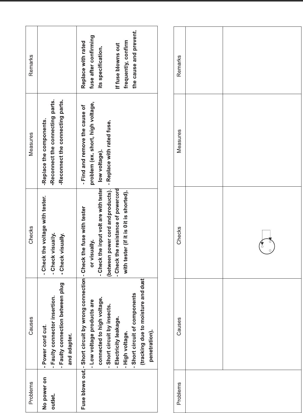
- Page 338. TROUBLE DIAGNOSIS 1. TroubleShooting CLAIMS. CAUSES AND CHECK POINTS. HOW TO CHECK 1) No power at outlet. * Measuring instrument: 1. Faulty start 2) No power on cord. Multi tester Bad connection between adapter and outlet. (faulty adapter) Check the voltage. The Inner diameter of adapter. If the
- Page 34CLAIMS. CAUSES AND CHECK POINTS. HOW TO CHECK 2. No cooling. 2) Refrigeration system is clogged. • Heat a clogged evaporator to Moisture Residual moisture check it. As soon as the Air Blowing. Not performed. clogged. in the evaporator. cracking sound starts, the Too short. evaporator will begin to I
- Page 35CLAIMS. CAUSES AND CHECK POINTS. HOW TO CHECK 3. Refrigeration 1) Refrigerant Partly leaked. Weld joint leak. is weak. Parts leak. 2) Poor defrosting capacity. • Check visually. Drain path (pipe) clogged. Inject adiabatics into drainInject through the hose. hole. Seal with drain. Foreign materials A
- Page 36CLAIMS. CAUSES AND CHECK POINTS. HOW TO CHECK 3. Refrigeration Residual Weak heat from heater. Sheath Heater - rated. is weak. frost. Heater plate No contact to drain. Loosened stopper cord. Heater cord-L Not touching the evaporator pipe. Location of assembly (top and middle). Too short defrosting t
- Page 37CLAIMS. CAUSES AND CHECK POINTS. HOW TO CHECK 3. Refrigeration 4) No cooling air circulation. is weak. Faulty fan motor. Fan is Fan shroud contact. - Clearance. constrained. Damping evaporator contact. Accumulated residual frost. Small cooling air Insufficient Fan overload. - Fan misuse. discharge.
- Page 38CLAIMS. CAUSES AND CHECK POINTS. HOW TO CHECK 4. Warm 1) Colgged cooling path. refrigerator Adiabatics liquid leak. compartment Foreign materials. –– Adiabatics dump liquid. temperature. 2) Food storate. Store hot food. Store too much at once. Door open. Packages block air flow. 5. No automatic 1) F
- Page 39CLAIMS. CAUSES AND CHECK POINTS. HOW TO CHECK 6. Condensation 4) Condensation on door. and ice Condensation on the duct door. - Duct door heater is cut. formation. Condensation on the Recess Heater is cut. dispense recess. Duct door is open. / Foreign material clogging. Condensation on the Not fully
- Page 40CLAIMS. CAUSES AND CHECK POINTS. HOW TO CHECK 7. Sounds 1) Compressor compartment operating sounds. Transformer sound. Its own fault. - Core gap. Bad connection. - Correct screw connection. Drip tray vibration sound. Bad assembly. Distortion. Foreign materials inside. Back cover machine sound. Bad c
- Page 41CLAIMS. CAUSES AND CHECK POINTS. HOW TO CHECK 8. Faulty lamp 1) Lamp problem. Filament blows out. (freezer and Glass is broken. refrigerator 2) Bad lamp assembly. Not inserted. compartment). Loosened by vibration. 3) Bad lamp socket. Disconnection. Bad soldering. Bad rivet contact. Short. Water pene
- Page 42CLAIMS. CAUSES AND CHECK POINTS. HOW TO CHECK 10. Structure, 1) Door foam. appearance, Sag. Hinge loose Bolt is loosened during and others. transportation. Not tightly fastened. Screw worn out . Weak gasket Adhesion surface. adhesion. Fixed tape. Not well fixed. Noise during Hinge interference. Bigg
- Page 432. FAULTS 2-1. Power 2-2. Compressor - Check that PTC model its ok, - If model its incorrect replace it. PTC Model: Compressor - Faulty PTC then check continuity between PTHTM 6R8MB doesn’t operate terminals 2 and 5 of PTC. - If there isn’t continuity replace it. - Faulty OLP - Check that OLP model
- Page 442-3. Temperature Problems Causes Checks Measures Remarks High Poor cool air circulation due to faulty - Lock –– Check resistance with a - Replace fan motor. temperature fan motor. tester. in the freezer 0 : short. compartment. : cut. - Reconnect and reinsert. - Rotate rotor manually and check rotati
- Page 452-4. Cooling Problems Causes Checks Measures Remarks High Refrigerant leak. Check sequence Weld the leaking part, recharge the Drier must be replaced. temperature 1. Check the welded parts of the refrigerant. in the freezer drier inlet and outlet and drier compartment. auxiliary in the compressor co
- Page 46Problems Causes Checks Measures Remarks High Cycle pipe is clogged. Check sequence. - Heat up compressor discharging Direr must be replaced. temperature in 1. Check temperature of condenser weld joints with touch, disconnect the freezer manually. the pipes, and check the clogging. compartment. If it
- Page 472-5. Defrosting failure Problems Causes Checks Measures Remarks No defrosting. Heater does not generate heat as 1. Check the resistance of heater. Heating wire is short and wire is lead cut. wire Seal with the the heating wire is cut or the circuit 0 : Short. : Cut. • Parts replacement: Refer to par
- Page 48Problems Causes Checks Measures Remarks No defrosting Melting fuse blows. - Check melting fuse with tester. - Faullty parts: parts replacement. 1) Lead wire is cut. If 0 : OK. - Check wire color when maeasuring 2) Bad soldering. If : wire is cut. resistance with a tester. Ice in the Suction duct. 1.
- Page 492-6. Icing Problems Causes Checks Measures Remarks Icing in the 1) Bad circulation of cool air. - Check the food is stored properly - Be acquainted with how to use.st - Check the defro refrigerator - Clogged intake port in the (check discharge and intake port - Sealing on connecting parts. em relate
- Page 50Problem Cause Check Measure Remarks Ice in the freezer 1) Bad cooling air circulation. - Check food storage conditions - Be acquainted with how to use.arts related - Check the p compartment. - Intake port is clogged in the freezer visually.(Check clogging at intake - Check defrost (Check ice on the
- Page 512-7. Sound Problems Causes Checks Measures Remarks Hisssound 1. Loud sound of compressor 1.1 Check the level of the 1) Maintain horizontal level. operation. refrigerator. 2) Replace bushing and seat if they 1.2 Check the bushing seat are sagged and aged. conditions (sagging and aging). 3) Touch the
- Page 52Problems Causes Checks Measures Remarks Vibration sound. 1. Vibration of shelves and foods in 1-1. Remove and replace the 1) Reassemble the vibrating parts Clack. the refrigerator. shelves in the refrigerator and insert foam or cushion where 2. Pipes interference and capillary 1-2. Check light food
- Page 53Problems Causes Checks Measures Remarks Sound Popping It happens when refrigerant expands - Check the sound of refrigerant at the - Check the restrainer attached on the (almost the same at the end of capillary tube. initial installation. evaporator and capillary tube weld as animals crying - Check t
- Page 542-8. Odor Problems Causes Checks Measures Remarks Food Odor. Food (garlic, kimchi, etc) - Check the food is not wrapped. - Dry the deodorizer in a sunny place - Check the shelves or inner with adequate ventilation. wall are stained with food juice. - Store the food in the closed - Be sure food is se
- Page 559. PCB 9-1. Main PCB P/N:EBR787482** CON 7 CON 8 CON 201 CON 6 CON 5 CON 1 CON 3 9-2. Display PCB (P/N: EBR797498**) CON101�
- Page 5610. TROUBLESHOOTING WITH ERROR DISPLAY 10-1. Freezer Sensor Error (Er FS) Symptom Check Point 1. Er FS 1. Check for a loose connection 2. Check Sensor Resistance CON8 Resistance [Ω] Short 0 CON8 Open OFF 23th pin ~ 24th pin Other Normal CON8 Resistance [Ω] 23th pin ~ 24th pin -22ºF / -30ºC 40k -13ºF
- Page 57Freezer Sensor Error (Er FS) 1 4 Reconnect or Is the Connector disconnected Yes repair the Check the Sensor resistance. or loose between Main PCB and connector Is resistance normal? sensor? Yes 5 Check the Temperature and resistance refer to the table. CON8 No problem? CON8 No Resistance [Ω] 23th pi
- Page 5810-2. Refrigerator Sensor Error (Er rS) Symptom Check Point 1. Er rS 1. Check for a loose connection 2. Check Sensor Resistance CON7 Resistance [Ω] Short 0 CON7 Open OFF 19th pin ~ 20th pin Other Normal CON7 Resistance [Ω] 19th pin ~ 20th pin 23ºF / -5ºC 38k 32ºF / 0ºC 30k 41ºF / 5ºC 24k 50ºF / 10ºC
- Page 59Refrigerator Sensor Error ( Er rS) 1 4 Reconnect or Is the Connector disconnected Yes repair the Check the Sensor resistance. or loose between Main PCB and connector Is resistance normal? sensor? Yes 5 Check the Temperature and resistance refer to the table. No problem? CON7 CON7 No Resistance [Ω] 1
- Page 6010-3. Refrigerator Sensor Error (Er r2) Symptom Check Point 1. Er R2 1. Check for a loose connection 2. Check Sensor Resistance CON7 Resistance [Ω] Short 0 CON7 Open OFF 17th pin ~ 18th pin Other Normal CON7 Resistance [Ω] 17th pin ~ 18th pin 23ºF / -5ºC 38k 32ºF / 0ºC 30k 41ºF / 5ºC 24k 50ºF / 10ºC
- Page 61Refrigerator Sensor Error ( Er r2) 1 4 Reconnect or Is the Connector disconnected Yes repair the Check the Sensor resistance. or loose between Main PCB and connector Is resistance normal? sensor? Yes 5 Check the Temperature and resistance refer to the table. No problem? CON7 CON7 No Resistance [Ω] 1
- Page 6210-4. Refrigerator Sensor Error (Er rT) Symptom Check Point 1. Er RT 1. Check for a loose connection 2. Check Sensor Resistance CON5 Resistance [Ω] Short 0 CON5 Open OFF 13th pin ~ 14th pin Other Normal CON5 Resistance [Ω] 13th pin ~ 14th pin 23ºF / -5ºC 38k 32ºF / 0ºC 30k 41ºF / 5ºC 24k 50ºF / 10ºC
- Page 63Refrigerator Sensor Error ( Er RT) 1 4 Reconnect or Is the Connector disconnected Yes repair the Check the Sensor resistance. or loose between Main PCB and connector Is resistance normal? sensor? Yes 5 Check the Temperature and resistance refer to the table. No problem? CON5 CON5 No Resistance [Ω] 1
- Page 6410-5. Defrost Sensor Error (F dS) Symptom Check Point 1. F dS 1. Check for a loose connection 2. Check Sensor Resistance CON8 Resistance [Ω] Short 0 CON8 Open OFF 21th pin ~ 22h pin Other Normal CON8 Resistance [Ω] 21th pin ~ 22th pin 23ºF / -5ºC 38k 32ºF / 0ºC 30k 41ºF / 5ºC 24k 50ºF / 10ºC 19.5k 5
- Page 65Icing Sensor Error (F dS) 1 4 Reconnect or Is the Connector disconnected Yes repair the Check the Sensor resistance. or loose between Main PCB and connector Is resistance normal? sensor? Yes 5 Check the Temperature and resistance refer to the table. No problem? CON8 CON8 Resistance [Ω] No 21st pin ~
- Page 6610-6. Defrost Heater Error (F dH) Symptom Check Point 1. F dH 1. Check the door gasket 2. Check the Defrost control part 3. Check the PCB output voltage CON3 Part Resistance [Ω] FUSE-M 0 Defrost Heater 48~54 Defrost Sensor 22k↑ TEST MODE 2 Voltage [V] CON3 112V ~ 116V 5nd pin ~ 6 th pin TEST MODE 1
- Page 67Defrost Heater Error (F dH) 1 4 Input Test 2 Mode Replace the (Push the button 3 times) Replace Check the Door gasket . Yes Door gasket Check the Heater Voltage. NO Main PCB Is door gasket damaged? Is voltage 112~116V? No CON3 2 Change TEST MODE 2 Voltage [V] Check the Defrost control part. No Fuse-
- Page 6810-7. Freezer Fan Error (Er FF) Symptom Check Point 1. Er FF 1. Check the air flow 2. Check the Fan Motor 2. Check the PCB Fan motor voltage Fan Motor CON8 TEST MODE 1 Voltage [V] CON8 8~12V 9th pin ~ 12th pin CON8 Not 0V, 5V 9th pin ~ 10th pin�
- Page 69Freezer Fan Error (Er FF) 1 Reset the unit and 4 Input Test1 Mode. Replace (Push the button 1 time) Check the Fan Motor voltage No Main PCB Is Fan Motor voltage 8~12V? CON8 2 TEST MODE 1 Voltage [V] Open the freezer door and Check No Go to 3 CON8 the air flow. Windy? 8~12V 9th pin ~ 12th pin Yes 5 C
- Page 7010-8. Condenser Fan Error (Er CF) Symptom Check Point 1. Er CF 1. Check the air flow 2. Check the Connector 2. Check the PCB Fan motor voltage Fan Motor CON8 TEST MODE 1 Voltage [V] CON8 8~12V 11 th pin ~ 16th pin CON8 Not 0V, 5V 11 nd pin ~ 14th pin�
- Page 71Condenser Fan Error ( Er CF) 1 Reset the unit and 4 Input Test1 Mode. Replace (Push the button 1 time) Check the Fan Motor voltage No Main PCB Is Fan Motor voltage 8~12V? CON8 2 TEST MODE 1 Voltage [V] Check the fan rotating. No Go to 3 CON8 Does fan rotate? 8~12V 14th pin ~ 16th pin Yes 5 Change th
- Page 7210-9. Communication Error (Er CO) Symptom Check Point 1. Er CO 1. Check the loose connection 2. Check the Hinge connection CON5 CON101 Display CON101 Voltage [V] CON101 12V 7rd pin ~ 8 th pin CON101 Not 0V, 5V 7th pin ~ 6th pin CON101 Not 0V, 5V 7st pin ~ 5rd pin CON5 Not 0V, 5V 15th pin ~ 17th pin
- Page 73Communication Error (Er CO) 4 Change the Check the voltage. Yes Main PCB Is CON101 7st pin ~ 5rd pin 1 voltage 0V or 5V? Check the loose connection Voltage Housing [V] CON101 Not 7th pin ~ 5th pin 0V, 5V 2 Check the Check the voltage. No Hinge (loose Is CON101 7rd pin ~ 8th pin connection) No voltag
- Page 7411. TROUBLESHOOTING WITHOUT ERROR DISPLAY 11-1. Cube mode doesn’t work Symptom Check Point 1. Cube mode 1. Check the loose connection doesn’t work 2. Check the resistance Duc Motor Ice Maker Auger Motor Dispenser SW
- Page 75INSPECTION POINT LEVER S/W Result Lever SW Pushing 0~2V CON6 Not 19th pin ~ 20th pin 3.5~5V Pushing Duct Motor Pushing 9~12V CON6 Not 23th pin ~ 24th pin 0~2V Pushing Motor Type Resistance [Ω] Auger Motor ( Pushing 112~115V Auger Motor 23.7 ~ 26.2 CON6 Not 3th pin ~ 7th pin 0~2V Duct Motor 9.9 ~ 12.
- Page 764 Check the resistance value. Replace Is Dispenser Motor resistance No Geared Motor 9.9 ~ 12.1Ω? Cube mode doesn't work 1 Check the loose connection Dispenser Motor 2 Change the No PCB Resistance [Ω] Check the voltage. (while pushing the lever S/W) Dispenser Motor 9.9 ~ 12.1 Is voltage correct compa
- Page 7711-2 Crush mode doesn’t work Symptom Check Point 1. Crush mode 1. Check the loose connection doesn’t work 2. Check the resistance Duc Motor Ice Maker Auger Motor Dispenser SW
- Page 78INSPECTION LEVER S/W Result POINT Lever SW Pushing 0~2V CON6 Not 19th pin ~ 20th pin 3.5~5V Pushing Duct Motor Pushing 9~12V CON6 Not 23th pin ~ 24th pin 0~2V Pushing Motor Type Resistance [Ω] Auger Motor ( Pushing 112~115V Auger Motor 33.2 ~ 36.7 CON6 Not 3th pin ~ 8th pin 0~2V Duct Motor 9.9 ~ 12.
- Page 794 Check the resistance value. Replace Is Dispenser Motor resistance No Geared Motor 9.9 ~ 12.1Ω? Crush mode doesn't work 1 Check the loose connection Dispenser Motor 2 Change the No PCB Resistance [Ω] Check the voltage. (while pushing the lever S/W) Dispenser Motor 9.9 ~ 12.1 Is voltage correct comp
- Page 8011-3. Water mode doesn’t work Symptom Check Point 1. Water mode 1. Check the loose connection doesn’t work 2. Check the resistance valve (1) (2) (3) (4) CON3 Pilot Valve Water Valve Machine Room In door LEVER S/W Voltage [V] CON3 Pushing 112~115V 10nd pin ~11 th Not pin 0~2V Pushing Resistance [Ω] P
- Page 81Water mode doesn't work 1 4 Replace Check the loose connection No Water Valve Check the resistance value. Is Water Valve resistance 360~420 Ω? 2 Change the Check the voltage. No PCB (while pushing the lever S/W) Is voltage correct? Water Valve Resistance [Ω] CON3 Water valve 360~420 LEVER S/W Voltag
- Page 8211-4. Refrigerator room led doesn’t work Symptom Check Point 1. Refrigerator room led 1. Check the freezer door switch sticky doesn’t work 2. Check the door S/W resistance 3. Check the LED Lamp Door S/W CON7 R Led Lamp Resistance [Ω] Open Infinity Door S/W Closed 0 Voltage [V] R LED CON7 12V 7th pin
- Page 83Refrigerator room lamp doesn’t work 1 4 Change the Change the Check the Freezer door switch. Yes Door S/W Check the LED Lamp voltage. No Door S/W Does it feel sticky? Is it 0~2V? (While door closed) No 2 Yes Change the Check the door S/W resistance. No Door S/W Is it correct compared with table? 5 C
- Page 8411-5. Freezer room lamp doesn’t work Symptom Check Point 1. Freezer room lamp 1. Check the Refrigerator door switch sticky doesn’t work 2. Check the door S/W resistance 3. Check the LED Lamp CON8 F room LED Door S/W Resistance [Ω] Normal Infinity Door S/W Push S/W 0 Voltage [V] CON8 12V 17th pin ~ 1
- Page 85Freezer room lamp doesn’t work 1 4 Change the Change the Check the Refrigerator door switch. Yes Door S/W Check the LED Lamp voltage No LED Lamp Does it feel sticky? Is voltage 12V? (While door open) No 2 Yes Change the Check the door S/W resistance. No Door S/W 7 Is it correct compared with table?
- Page 8611-6. Poor/Over cooling in Fresh food section Symptom Check Point 1. Poor cooling in Fresh 1. Check the sensor resistance food section 2. Check the air flow 3. Check the air Temperature 4. Check the R-Damper motor voltage CON7 Duct CON8 Fan Motor CON7 R1SNR Resistance 19th pin ~ 20th pin [Ω] 23ºF /-
- Page 87Poor cooling in Fresh food section 4 Check the Check the air temperature. No Compressor Is it cold? and sealed 1 system Check the sensor resistance. Yes Go to 7 CON7 CON7 R1SNR 5 19th pin ~ 20th pin Resistance [Ω] Check the Fan Motor voltage Is Fan Motor voltage 8~12V? Replace No 23ºF / -5ºC 38k Mai
- Page 8811-7. Poor cooling in Freezer compartment Symptom Check Point 1. Poor cooling in 1. Check the sensor resistance Freezer compartment 2. Check the air flow 3. Check the air Temperature 4.Check the Fan motor sticky 4. Check the Fan motor voltage Duct Fan Motor CON8 CON8 Resistance 23 th pin ~ 24th pin
- Page 89Poor cooling in Freezer compartment 4 Check the Check the air temperature. No Compressor Is it cold? and sealed 1 Check the sensor resistance. system Yes CON8 5 Change the CON8 Resistance Yes Check the Fan motor. Fan motor 23 th pin ~ 24th pin [Ω] Rotate fan using hand. -22ºF / -30ºC 40k It feel sti
- Page 906 Replace Check the Fan Motor voltage No Main PCB Is Fan Motor voltage 8~12V? CON8 TEST MODE 1 Voltage [V] CON8 8~12V 9th pin ~ 12th pin Yes 7 Change the Check the Fan Motor voltage Yes motor Is Fan Feed Back voltage 0V, 5V? CON8 TEST MODE 1 Voltage [V] CON8 Not 0V, 5V 9th pin ~ 10th pin No 8 Explai
- Page 914. Appendix 19) Entering to the Test Mode How to make TEST MODE TEST MODE 1 If refrigerator is in NORMAL MODE, press once TEST S/W in Main PCB. TEST 1 Display Response in TEST MODE 1 If any error is present, you can not enter to TEST MODE. TEST MODE 2 If refrigerator is in NORMAL MODE, press twice T
- Page 92How to make DISPLAY CHECK MODE In order to check hidden error codes, or Display functionality. To enter to this mode in Elite 3 press simultaneously ICE PLUS button and FREEZER button for more than 5 seconds. If no are errors detected, all LED’s will be turned ON, otherwise, error code will be displ
- Page 9320) Removing TPA’s (Terminal Position Assurance) How to remove Terminal Position Assurance (TPA)
After measure the values, you should put in the TPA again. 3. Wire Color BL: Blue GN: Green WH: White SB: Sky Blue BO: Bright Orange GY: Gray BK: Black BL/WH: Blue & White BN: Brown WH/ - Page 9421) Temperature Charts Temperature Chart #1 Temperature Chart #2 Temperature Resistance KÙ Voltage Temperature Resistance KÙ Voltage -40°F / (-40°C) 73.29 4.10 -40°F / (-40°C) 225.10 4.48 -31°F / (-35°C) 53.63 3.84 -31°F / (-35°C) 169.80 4.33 -22°F / (-30°C) 39.66 3.55 -22°F / (-30°C) 129.30 4.16 -1
- Page 953. SEALED SYSTEM HEAVY REPAIR 3-1. Summary of heavy repair Process Contents Tools Trouble diagnosis Remove refrigerant - Cut charging pipe ends and discharge refrigerant from Filter, side cutters Residuals drier and compressor. - Use R134a oil and refrigerant for compressor and drier Pipe Cutter, Ga
- Page 963-2. Precautions During Heavy Repair Items Precautions 1. Use of tools. 1) Use special parts and tools for R134a. 2. Recovery of refrigerant. 1) Continue to recover the refrigerant for more than 5 minutes after turning the refrigerator off. 2) Install a piercing type valve on the high pressure line
- Page 973-3. Practical Work For Heavy Repair Items Precautions 1. Removal of residual refrigerant. Suction KEY POINT Observe the sequence for removal of refrigerant. (If not, compressor oil may Capillary leak.) Tube Service tube Discharge tube 1) Continue to recover the refrigerant for more than 5 minutes a
- Page 98Items Precautions 4. Vacuum degassing. Evaporator Suction pipe Hot Line Compressor Drier Condenser 3 2 1 Low pressure High Blue pressure Yellow Red KEY POINT Vaccum - If power is applied Pump during vacuum degassing, vacuum degassing shall be more effective. Pipe Connection - Run the compressor Conn
- Page 99Items Precautions Evaporator Hot Line Compressor Drier Condenser Charging Canister 4) Refrigerant Charging Charge refrigerant while operating a compressor as shown above. 5) Pinch the charging pipe with a pinch-off plier after completion of charging. 6) Braze the end of a pinched charging pipe with
- Page 1003-5. Brazing Reference Drawing�
- Page 1014. HOW TO DEAL WITH CLAIMS 4-1. Sound Problems Checks and Measures Hisssounds Explain general principles of sounds. • All refrigerators make noises when they run. The compressor and fan produce sounds. There is a fan in the freezer compartment which blows cool air to freezer and refrigerator compart
- Page 102Problems Checks and Measures Sounds of water flowing Explain the flow of refrigerant. • When the refrigerator stops, the water flowing sound happens. This sound happens when the liquid or vapor refrigerant flows from the evaporator to compressor. Click sounds Explain the characteristics of moving pa
- Page 1034-2. Measures for Symptoms on Temperature Problems Checks and Measures Refrigeration is weak. Check temperature set in the temperature control knob. • Refrigerator is generally delivered with the button set at normal use(MID). But customer can adjust the temperature set depending on their habit and
- Page 1044-3. Odor and Frost Problems Checks and Measures Odor in the refrigerator compartment. Explain the basic principles of food odor. • Each food has its own particular odor. Therefore it is impossible to prevent or avoid food odor completely when food is stored in the completely sealed refrigerator com
- Page 1054-4. Others Problems Checks and Measures The refrigerator case is hot. Explain the principles of radiator. • The radiator pipes are installed in the refrigerator case and partition plate between the refrigerator and the freezer compartment in order to prevent condensation formation. Particularly in
- Page 106#EV# 12.EXPLODED VIEW FREEZER DOOR 131C 606A 600A 200A 203A 201A 131D 212K 241F 244A 212J 212K 241G 241G 241G 243A�
- Page 107#EV# REFRIGERATOR DOOR 241A 241C 230A 241B 233A 231A 212G 241H 212K 244A 241J 212J 212K 241J 243B 241J�
- Page 108#EV# FREEZER COMPARTMENT 120D 281A 332A 271B 271A 330B 405G 610E 404A 158C 405A 329A LD3 316B 149C 301A 149B 401A 281G 106A 332B 418A 103C 319B 136A�
- Page 109#EV# REFRIGERATOR COMPARTMENT 281B 501C 158D 154A 271B 158A 271C 611E 170A 120B 128G 611B 120A 141A 128H 903D 610E 281K 281H 161A 151A 154A 106A 151B�
- Page 110#EV# ICE &WATER PARTS 625A 627D 625B 627B 623A 615A 607A 619A 616K 621B 278A 113G 405H 113F 280A 113E 282G�
- Page 111#EV# MECHANICAL COMPARTMENT 501F 103B 410G 411A S15 410H 501A 308A 103A 309A 304A 316A 419B 307A 314A 314A 105A 317A 328A 327A 319C 404B 329C 312A 319A 323B 315A�
- Page 112MFL62215929 August, 201�