Samsung Rf23Hcedtsr Page 107
Workshop Manuals
107107
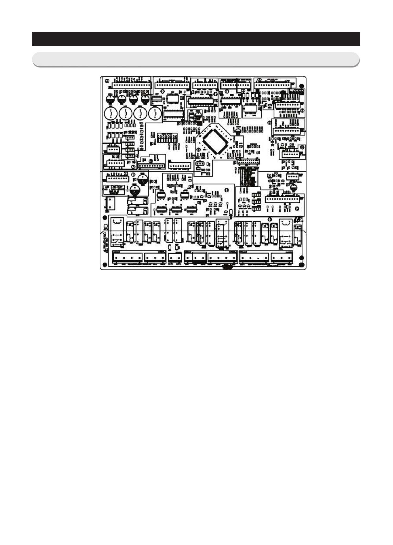
PCB DIAGRAMPCB DIAGRAM
This document can not be used without Samsung's authorizationThis document can not be used without Samsung's authorization
1. 1.
DC12V, 5V, DC12V, 5V,
GND supplieGND supplie
d from d from
SMPS PCB SMPS PCB
(Not Used)(Not Used)
2. 2.
Circuit for controlling Circuit for controlling
Step-Valve (3-Way Step-Valve (3-Way
Valve) * OValve) * O
ptionption
3. 3.
FAN MOTOR control part : To FAN MOTOR control part : To
supply the power from 8.3V supply the power from 8.3V
~ 12V according to the m~ 12V according to the m
otorotor
types. (F,R,C,ICE)types. (F,R,C,ICE)
4. 4.
EEPROM : SavEEPROM : Sav
e and record e and record
every kinds of every kinds of
data.data.
5. 5.
Transmit inputted signals from Transmit inputted signals from
every sensor into MICOevery sensor into MICO
M after eliminate the noisM after eliminate the nois
e.e.
6. 6.
Micom : control the reMicom : control the re
grigerator Ceramic resonagrigerator Ceramic resona
tor : generate the basic frequetor : generate the basic freque
ncy of Micomncy of Micom
operation.operation.
Reset IC : make Micom reset if Reset IC : make Micom reset if
input voltage of Micom is detected less tinput voltage of Micom is detected less t
han the specifiedhan the specified
voltagevoltage
7. 7.
PLC PLC
input/outputinput/output
- -
PLC (Power Line communication) * Option (PLC moPLC (Power Line communication) * Option (PLC mo
dule is not inserted unless specifieddule is not inserted unless specified
occasion)occasion)
8. 8.
Operate ICE-MAKER, supply Operate ICE-MAKER, supply
power to MOTOR, and sepower to MOTOR, and se
nse the variation of switchnse the variation of switch
..
9. 9.
Main Micom ↔ PaMain Micom ↔ Pa
nel Micom serial conel Micom serial co
mmunication circuit - Dispenmmunication circuit - Dispen
ser option input partser option input part
(Water & Cover Ice route switch)(Water & Cover Ice route switch)
10. 10.
Mid drawer Room display control part : Mid drawer Room display control part :
display LED, detect KEY state.display LED, detect KEY state.
11. 11.
Control Mid drawer Room damper & Damper heaterControl Mid drawer Room damper & Damper heater
12. Water Tank Heater Controls (also controls 12. Water Tank Heater Controls (also controls
other options)other options)
13. LE13. LE
D LAMP Control Circuit (F,R D LAMP Control Circuit (F,R
room Lamp)room Lamp)
14. Re14. Re
lay parts that controls AC load lay parts that controls AC load
and receives Micom operating signal through Sink IC.and receives Micom operating signal through Sink IC.
15. Con15. Con
nector with AC nector with AC
loadload
a. Diode option setting areaa. Diode option setting area
b. Inverter COMP controlling signalb. Inverter COMP controlling signal
c. Flow Sensor controlling signalc. Flow Sensor controlling signal
16. WiFi Module Function input/output16. WiFi Module Function input/output
5-1) PBA Layout with part position5-1) PBA Layout with part position
Contents Summary of Samsung Rf23Hcedtsr
- Page 1REFRIGERATOR FRENCH DOOR REFRIGERATOR BASIC : RF23HC* MODEL NAME : RF23HCEDTSR RF23HCEDBSR RF23HCEDBBC RF23HCEDBWW MODEL CODE : RF23HCEDTSR/AA RF23HCEDBSR/AA RF23HCEDBBC/AA RF23HCEDBWW/AA REFRIGERATOR CONTENTS 1. PRECAUTIONS(SAFETY WAR WARNINGS) NINGS) ·············· 5 2. PRODUCT SPECIFICA SPECIFICA
- Page 2WARNING IMPORTANT SAFETY NOTICE The service guide is is for service men with with adequate backgrounds backgrounds of electrical, electrical, electronic, and mechanical experience. Any attempt to repair a major appliance may result in personal injury and property damage. damage. The manufacturer or
- Page 3Contents 1. Precautions(S Precautions(Safety afety Warnings) ....................................................................5 2. Product Specificati Specifications ons .............................................................................9 2-1) Introduction of Main Function ............
- Page 4Contents 3-30) Electric Box........ Box...................... ........................... .......................... .......................... .......................... .......................... .......................... .......................... ............... ..5555 3-31) Disassemble the WIF
- Page 51. Precautions(Safety Precautions(Safety Warnings) Warnings) ● Unplug the appliance before the changing or repairing the electric parts. ➝ Be careful the electric shock. ● Always use only the correct replacement parts. ➝ Check the model, rated voltage, rated current and running temperature temperatu
- Page 6Precautions(Safety Warnings) Read all instructions before repairing the product and follow the instructions in order to prevent danger or property damage. Plug out and remove all the items in regrigerator prior to repair. CAUTION/WARNING SYMBOLS DISPLAYED SYMBOLS means “Prohibited”. Indicates that a
- Page 7Precautions(Safety Warnings) ❈Please let users know following warnings & cautions in detail. Warning & Caution Customers should not store glass Customers should not store narrow Drugs requiring precise bottles of liquid in the freezer or long bottles or food in a small temperatures temperature s sh
- Page 8Precautions(Safety Warnings) FLOORING For proper installation, this refrigerator must be placed on a level surface of hard material that is the same height as the rest of the flooring. This surface should be strong enough to support a fully loaded refrigerator. MOVING Protect the finish of the floor
- Page 92. Product Specifications 2-1) Introduction of Main Function ............ ......................... .......................... .......................... .......................... .......................... ........................ ........... 10 2-2) Specifications ............ ...................
- Page 10Product Specifications 2-1) Introduction of Main Function A newly developed SAMSUNG FRENCH DOOR REFRIGERATOR in 2014 has the following characterist characteristics. ics. Surround Multi Flow • Uniform Uniform cooling for each shelf and even in corner in fresh food compartment by centerpositioned fan
- Page 11Product Specifications Secure Auto Close Door System • Secure Secure Auto Close Door System • Cool Cool tight doors • Energy saving • Preventing Preventing sweat on fridge doors Easy Handle System • Ez-open Freezer Door • Ergonomic Ergonomic Door Design - The freezer door is more user-friendly. So,
- Page 12Product Specifications 2-2) Specifications ELECTRICAL SPECIFICATIONS REFRIGERATOR Defrost Control From 12 to 30hrs(comp. run time) Th er erm o Bime ta tal Pr Pr ot otect or or 1 40 40°F(60° C) C)( of off) 10 10 4° 4°F(40° C) C)( on on) Defrost Thermistor(502AT) 50°F(10℃)(off) Fan Electrical Rating A
- Page 13Product Specifications 2-3) Interior Views Light Refrigerator FR Ice-Maker Cover Evap (Light) Dis Door Bins Fixed Shelf Cap Chute Right Door Bins Vertical Hinged Section Light Slide-Shelf Mid Door Bins Quick-Space Glass Shelf Vegetable & Cover Veg Fruit Drawers Left Door Bins Cool Select Water Filte
- Page 14Product Specifications 2-4) Model Specification SAMSUNG ITEM SPEC RF23HC** Appearance Cooling Tech Twin Cooling Product Zone Door Shape Contour Special Room Cool Select Pantry Cooling F-Room 202↓ 1 61 Speed(Min) R-Room 205.0↓ 185 F-Room -31.5↓ -32.8 e 89.6 (32°C) c R-Room 1.7↓ -0.9 n a m r F-Room -2
- Page 15Product Specifications RF23HC** ITEM Model Ice & Water Dispenser with Pantry W 35 6/8 Inch (908mm) (908mm) On Cabinet 24 Inch (613mm) D W/O Handle 28 1/2 Inch (726mm) External size With Handle 31 Inch (788mm) W/O Hinge Cap 68 7/8 Inch (1749mm) (1749mm) H With Hinge Cap 70 Inch (1777mm) Total 22.5 Cu
- Page 16Product Specifications Items Specification Model RF23HC** Model MKV190CL2B/E01 r Compressor Starting type BLDC e z e Oil Charge FREOL α - 15c e r F r Freezer SPLIT FIN TYPE o f Evaporator s t Refrigerator SPLIT FIN TYPE n e n Condenser Forced and Natural Convection Type o p m Dryer Molecular shieve
- Page 17Product Specifications Items Specification Model RF23HC** Defrost Heater(FRE) Heated at F Defrost AC120V, 230W Defrost Heater(REF) Heated at R Defrost AC120V, 100W Heater-Ice Maker AC120V, 120W Interlock with French AC 120V, 2.5W DISPENSER Heater Heater FRENCH Heater - AC120V, 12W R-ROOM DC12V, 2.3W
- Page 18Product Specifications 2-5) Dimensions of Refrigerator (Inches) Model : RF23HC** 35 6/8"(908mm) ) m m 5 3 7 ( " 6 ) 1 / 5 m 1 ) m 8 m 6 2 1 m 1 ) 7 1 m 7 ( 2 " m 1 8 2 ( / 0 " 7 1 ( 4 " / 3 6 1 ) 4 1 / 0 m 1 5 m 4 5 ) 7 m 4 ( m " 0 4 4 / 4 ( 3 " 8 6 1 1 / 5 7 1 61 2/3" (1568 mm) 31" (788mm) 28 1/2"
- Page 19Product Specifications 2-6) Optional Material Specification Part Name Part Code AMOUNT ASSY-PACKING SUB DA99-03490L 1 LED LAMP REF DA97-12606A 1 LED LAMP CASE-VEG R, L DA41-00519S 1 LED LAMP REF(SIDE) DA41-00519Q 2 LED LAMP FRE DA41-00676G 1 19
- Page 20Product Specifications 2-7) Refrigerant Route in Refrigeration cycle Compressor → Sub-condenser → Pipe hot → Pipe cluster-rear → Dryer → Capillary tube → Refrigerator Evaporator → Pipe cooling → Pipe connect R-F → Freezer evaporator → Suction pipe → Pipe connect suction → Compressor 20
- Page 21Product Specifications 2-7-1. PRINCIPLE OF FREEZEER 21
- Page 22Product Specifications 2-7-2. Operation theory of refrigeration cycle components ■Condenser 1) Role: A device which radiates heat heat to the outside of the refrigerator refrigerator.. As this heat is dispersed, the high temperature/ high pressure vapor refrigerant changes to a liquid state. 2) Type
- Page 23Product Specifications ■Evaporator 1. Role: As the low pressure pressure liquid refrigerant refrigerant flowed from capillary absorbs heat inside of the refrigerator, it becomes low pressure gas and refrigerate the foods. 2. Theory: Theory: The low pressure pressure refrigerant flowed to evaporator
- Page 24Product Specifications 2-8) Cooling Air Circulation 24
- Page 253. Disassembly and Reassembly 3-1) PRECAUTION ............. .......................... .......................... .......................... .......................... .......................... .......................... .......................... .......................26 ..........26 3-2) Refrige
- Page 26Disassembly and Reassembly 3-1) PRECAUTION • Unplug the refrigerator before cleaning and making repairs. • Do not dissemble or repair the refrigerator by yourself. - It may cause risk of causing a fire, malfunction and/or personal personal injury. • Remove any foreign matter or dust from the power p
- Page 27Disassembly and Reassembly 3-2) Refrigerator Door Part Name How To Do Descriptive Picture 1. Remove the 3 screws holding down the Top Table and remove the Top Table () 2. Disconnect the electrical () above the upper left door hinge To disconnect the connector ( ) more easily, press the end of
- Page 28Disassembly and Reassembly Part Name How To Do Descriptive Picture 5. Lift the door straightly up to remove. Refrigerator Door 6. With a Philips head head screwdriver, remove the screw () attatched to the lower left and right door hinges. With a wrench(0.4"), wrench(0.4"), remove the 2 flat head
- Page 29Disassembly and Reassembly 3-4) Door Handle Freezer & Flex zone Part Name How To Do Descriptive Picture 1. Loosen the Set Screw situated at the bottom right of the appliance about 0.1in by using Hex wrench. Door Handle Freezer 2. Pull the Set Set handle out by moving moving it to the right side. Be
- Page 30Disassembly and Reassembly 3-5) Refrigerator Light Part Name How To Do Descriptive Picture 1. Press the tabs on the back of the Lamp Cover and take it off. Refrigerator Light 2. Remove the 2 screws And And separate the LED panel. 30
- Page 31Disassembly and Reassembly 3-6) Cover-Display & Water-Dispenser Part Name How To Do Descriptive Picture 1. Remove a screwscrew under the display cover. 2. Remove the display cover by pulling it up. Put the thumbs on the surface door and hold the bottom of the t he Display Panel with four fingers. An
- Page 32Disassembly and Reassembly 3-7) Water-Dispenser Part Name How To Do Descriptive Picture 1. Disengage the Housing Connector by pushing a flat-blade screwdriver. 2. Remove 2 screws of the Case Ice Route Assy. Water-Dispenser Water-Dispen ser 3. Pull the Case Case Ice Route Assy. 4. Assembly shall shal
- Page 33Disassembly and Reassembly 3-8) Glass Shelf Part Name How To Do Descriptive Picture 1. Remove the shelf shelf by lifting the front Glass Shelf part of the shelf up and pulling it out. 3-9) Foldable Glass Shelf Part Name How To Do Descriptive Picture Foldable Glass 1. Remove 2 screws screws of the Fo
- Page 34Disassembly and Reassembly 3-10) Vegetable & Fruit Drawers Shelf Part Name How To Do Descriptive Picture 1. Remove the vegetable & fruit drawer by pulling the roller part and lifting it up. Vegetable & Fruit Drawers Shelf 2. Remove the vegetable vegetable & fruit drawer shelf by pulling it out. (Ref
- Page 35Disassembly and Reassembly 3-11) Cool Select Pantry Part Name How To Do Descriptive Picture 1. Remove the cool select pantry by Cool Select Pantry pulling the roller part and lifting it up. 1. Remove the cool select pantry Cool Select Pantry cover by lifting up the left part of Cover the cover and p
- Page 36Disassembly and Reassembly 3-12) Cover Slide Pantry Part Name How To Do Descriptive Picture 1. Lift up the pantry cover. 2. Lift the left side of pantry cover straightly up to remove. 3. Take out thethe right side angle of pantry cover. 4. Complete the disassembly. Cover Slide Pantry 5. Insert the r
- Page 37Disassembly and Reassembly 3-13) Case Water Filter Part Name How To Do Descriptive Picture To disassemble the Case Water Filter, remove the water filter and all drawers and shelves. 1. Remove the 3 screws holding holding down the Top Table and remove the Top Table (). 2. a. Remove Cover Cover Tube
- Page 38Disassembly and Reassembly Part Name How To Do Descriptive Picture 5. Disconnect the 2 Housing connectors (). Case Water Filter 6. Lift and pull the Case Water Filter out. 3-14) Motor Damper Part Name How To Do Descriptive Picture 1. Remove the cool select pantry. Remove the screw of motor damper
- Page 39Disassembly and Reassembly 3-15) Water Filter (Assembly ( Assembly & Disassembly) Part Name How To Do Descriptive Picture 1. Turn the water filter count-clockwise. (Refer to the picture) 2. Remove the water filter by pulling it. (Refer to the picture) Water Filter 3. Push the water filter filter dir
- Page 40Disassembly and Reassembly 3-17) Door Bin left Middle Part Name How To Do Descriptive Picture 1. Pull The Gallon Gallon Door bin like like indicated indicated direction in picture. 2. Take the right side of the bin out by Door Bin left Middle lifting it at an angle along the guide. 3. . And then tak
- Page 41Disassembly and Reassembly 3-18) Vertical Hinged Section Part Name How To Do Descriptive Picture 1. Remove 2 screw screw caps with a flat- blade(-) screwdriver. (Refer to the picture) 2. Unscrew 2 screws. Vertical Hinged Section 3. Disengage the internal internal housing housing connector of the ver
- Page 42Disassembly and Reassembly 3-19) Evaporator Cover In Refrigerator Part Name How To Do Descriptive Picture 1. Remove the angle angle cap with a flat- blade screwdriver. (Refer to the picture) Be careful not to scratch or CAUTION break the parts. 2. Unscrew 4 screws. 3. Remove the the lower part of an
- Page 43Disassembly and Reassembly 3-20) Evaporator In Refrigerator Part Name How To Do Descriptive Picture
1. Disconnect the housing connector part on left side. Before doing the above, make sure that the unit is CAUTION unplugged. 2. Disconnect the housing housing connector connector Evapor - Page 44Disassembly and Reassembly 3-21) Super Extended Drawer Part Name How To Do Descriptive Picture 1. Slide the drawer in as much much as possible. Super Extended 2. Lift the drawer up. Drawer 3. Remove the drawer by lifting the bottom part of drawer bin and pulling it out. 44
- Page 45Disassembly and Reassembly 3-22) Freezer Door Part Name How To Do Descriptive Picture 1. Take outout the upper drawer drawer by lifting it up. 2. Remove the tilting Pocket (①) ② by pulling the both brackets (②) upward at the same time. ① 3. Take out the lower basket (③) Freezer Door by lifting the b
- Page 46Disassembly and Reassembly 3-23) Ice-Maker Part Name How To Do Descriptive Picture 1. When pressing the Energy-Saver and the Fridge buttons on the Display together for 8 seconds at the same time, it will convert to t o the Test Mode and the entire Display function will be off. 2. When pressing press
- Page 47Disassembly and Reassembly Part Name How To Do Descriptive Picture 7. Remove the screw from the Duct Tray-ice. 8. With a flat blade screwdriver, push the duct to the right and remove it from the locking tab. (Refer to the image.) 9. With a flat blade screwdriver, pry down on the refrigerant tube to
- Page 48Disassembly and Reassembly Part Name How To Do Descriptive Picture If the ice maker is frozen, it can be Ice Maker melt by using the steam heater. 1. Disconnect the FAN-AUGER-ASSY Connector. Auger Motor Fan 2. Hold the Hook on the bottom of the FAN-AUGER-ASSY and lift it up to make it free from the
- Page 49Disassembly and Reassembly 3-24) Freezer Light Part Name How To Do Descriptive Picture 1. Remove the cover Freezer lamp () using a flat-blade screwdriver. Freezer Light 2. Disengage the housing. Before doing the above, make CAUTION sure that the unit is unplugged. 3-25) Door Switch In Freezer Par
- Page 50Disassembly and Reassembly 3-26) Evaporator Cover in the freezer Part Name How To Do Descriptive Picture 1. In case case of Twin ice maker option, loosen the 2- screws and disconnect the housing connector. 2. Loosen the 2-crews on the Evaporator Cover in left/right evaporator cover, the freezer then
- Page 51Disassembly and Reassembly 3-27) Evaporator Cover in the freezer Part Name How To Do Descriptive Picture 1. Separate the steel cover and disconnect the 2- housing connectors on right side. Before conducting the work above, make CAUTION sure that the unit is unplugged. 2. Lift the pipe up carefully,
- Page 52Disassembly and Reassembly 3-28) Comp Cooling Fan Part Name How To Do Descriptive Picture 1. Unscrew 5 screws of COVER COMP. 2. Remove the DRAIN HOSE. HOSE. 3. Remove 1 screw. 4. Disengage the HOUSING Comp Cooling Fan CONNECTOR. (Refer to the picture) 5. Pull it forward and lean against the DRAIN HO
- Page 53Disassembly and Reassembly 3-29) Comp Cooling Fan Motor Part Name How To Do Descriptive Picture 1. Remove the screw screw with a flat blade screwdriver. 2. Remove thethe motor fan by pulling the fan out while graping the motor part. Comp Cooling Fan 3. Unscrew 2 screws fixed in the Motor motor. 4. R
- Page 54Disassembly and Reassembly Part Name How To Do Descriptive Picture 1. Disengage the housing connector. Relay O/L 2. Remove Cover Relay. 3. Remove the relay O/L with a flat- blade screwdriver. (Refer to the picture) 54
- Page 55Disassembly and Reassembly 3-30) Electric Box Part Name How To Do Descriptive Picture 1. Remove the 3 screwscrew attached attached to the upper left and right Case PCB Panel with a phillips screwdriver(+). 2. Disengage all housing housing connectors connectors from the main PCB. PBA Main Before doin
- Page 56Disassembly and Reassembly 3-31) Disassemble the WIFI module. Part Name How To Do Descriptive Picture 1. Disassemble the top- Table after loosen three screw which is supported the Top-Table. 2. Disassemble the 7PIN7PIN cable housing. Screw 1. Loosen a screw of WIFI module WIFI module which is in the
- Page 574. TROUBLESHOOTING 4-1) Function for failure diagnosis .............. ........................... .......................... .......................... .......................... .......................... ......................58 .........58 4-2) Diagnostic method according to the trouble symptom(F
- Page 58TROUBLESHOOTING 4-1) Function for failure diagnosis 4-1-1. Test mode (manual operation / manual defrost function) • If Freezer Key + Lighting Key on the front of panel are pressed simultaneously for 8 seconds , it will be changed to the test mode and all displays on the front of panel will be off. •
- Page 59TROUBLESHOOTING 2) Forced Defrost 2-1) When you press any key one more time at Fridge off Forced Operation [OF r], rd lights up on the Display Panel. At this time, the Forcd Operation stops immediately and R-Defrost will be performed at the same time. 2-2) When you press any key one more time at For
- Page 60TROUBLESHOOTING 4-1-3. Self-diagnostic function 1) Self-diagnostic function in the Initial power ON 1-1) Micom operates self-diagnostic function to check the temperature sensor condition within 1 second when the refrigerator turned On initiall initially. y. 1-2) If bad sensor is detected by the self
- Page 61TROUBLESHOOTING ※ R Self-diagnostics check list LED Item Trouble contents Diagnostic method F R When measuring the voltage between the Main FZ-Sensor Error PCB CN30-"4" ↔ CN76-"1", it should read between 4.5V~1.0V. When measuring the voltage between the Main FF-Sensor Error PCB CN30-"6" ↔ CN76-"1",
- Page 62TROUBLESHOOTING ※ R Self-diagnostics check list LED Item Trouble contents Diagnostic method F R After separating MAIN PCB CN77 wire from Display error when open error is detected PCB, resistance value between Black ↔ Brown Pantry-Damper- by damper heater : separation of Damper wire shall be 135 ohm±
- Page 63TROUBLESHOOTING 4-1-4. Display function of Load condition RF23HCEDB* RF23HCEDT* ① ① ① ① ② ② ① If Freezer Key + Fridge Key are pressed simultaneously simultaneously for 6 seconds, ALL ON/OFF will blink blink with 0.5interval for 4 seconds. ② If take the finger off from from above keys and press Light
- Page 64TROUBLESHOOTING ※ Load mode Check list Display LED Display contents Operation contents When FF compartment FAN operates with high speed, applicable R-1-ⓐ R-FAN High LED ON When FF compartment FAN operates with low speed, applicable R-1-ⓑ R-FAN Low LED ON R-1-ⓒ R-DEF Heater When FF compartment defros
- Page 65TROUBLESHOOTING 4-1-5. Cooling OFF mode setting function RF23HCEDB* RF23HCEDT* ① ① ① ① ① ① ① If Freezer Key + Fridge Ke y + Alarm Key are p ressed for 5 seconds, Cooling Off mode will be started. 1) If Freezer Key + Fridge K ey + Alarm Key are pressed simultaneously for 5 seconds during normal opera
- Page 66TROUBLESHOOTING 4-1-7. Option setting function • If Alarm Key + Fridge Key are pressed simultaneously for 12 seconds during normal operation, fresh food and freezer compartments temperature display will be changed to option setting mode. KEY operation method for changing to option mode RF23HCEDB* RF
- Page 67TROUBLESHOOTING Code Reference Value 1) For example, if you want to c hange freezer compartment standard temperature to -4℉(-2°C) by operating option, do as be low. This function function is for changing the standard temperature. In -2℉ (-19°C) of current temperature of freezer compartment, if you m
- Page 68TROUBLESHOOTING 4-1-8. Option TABLE 1) Temperature Temperature changing table t able of freezer compartment Set item Freezer Temp Shift MODEL RF23HC* Reference Fridge Room 7-SEG Value 0 Setting value FZ compartment Temp. Code compensation 0 0℉(0.0℃) 1 -1℉(-0.5℃) 2 -2℉(-1.0℃) 3 -3℉(-1.5℃) 4 -4℉(-2.0℃
- Page 69TROUBLESHOOTING 3) Eject waiting time changing table of freezer compartment Ice Maker (RF23HCEDT* Model only) Set item FZ-Room Ice Maker Eject waiting time Shift Reference Fridge Room 7-SEG Value 3 Setting value FZ compartment Setting time Code 0 58min 1 57min 2 56min 3 55min 4 54min 5 53min 6 52min
- Page 70TROUBLESHOOTING 5) Operation rate changing table of dispenser heater Set item Dispenser Heater Rate Reference Fridge Room 7-SEG Value 19 Setting value FZ compartment Rate change Code 0 +0.0% + 20% operation 1 ( up to 100% ) Code Reference Value ex) If you want to change the dispenser heater operatio
- Page 71TROUBLESHOOTING 7) Ice Tray water supply of fresh food compartment Ice Maker Set ititem R co compartment ICICE TRTRAY wa water susupply Reference Fridge Room 7-SEG Value 32 Setting value FZ compartment Water settings. Code 0 65cc 1 75cc 2 - 3 - 4 - 5 - 6 - 7 - 8) Eject waiting time changing table of
- Page 72TROUBLESHOOTING 9) Temperature Temperature changing table t able of fresh food compartment Ice Maker. Set item Freezer Temp Shift MODEL RF23HC* Reference Fridge Room 7-SEG Value 34 Setting value FZ compartment Temp. Code compensation 0 0℉(0.0℃) 1 -1℉(-0.5℃) 2 -2℉(-1.0℃) 3 -3℉(-1.5℃) 4 -4℉(-2.0℃) 5 -
- Page 73TROUBLESHOOTING 4-2) Diagnostic method according to the trouble symptom(Flow Chart) DATA1.Temperature table Resistance value and MICOM port voltage of sensor according to the temperature SENSOR CHIP : based on PX41C, PX41C, 502AT/ 103**(ICE MAKER SENSOR(MOLD)/FULL UP, 20Kohm ( Actual measurement = v
- Page 74TROUBLESHOOTING DATA2. Humidity Sensor table - Voltage output table @23°…, 5Vdc --- HTG3515CH/HTG3535CH RH(Temperature RH(T emperature compensate ) = RH (Relative Humidity ) + ( Temp(°C) Temp(°C) °© 23°C) x 0.05 ℃ ℉ Vol Voltage tage Resistance ℃ ℉ Voltage tage Resistance ℃ ℉ Voltage tage Resistance
- Page 75TROUBLESHOOTING 4-2-1. If the trouble is detected by self-diagno self-diagnosis sis - The error of sensor will be displayed on the front of display. when the error of sensor is detected at initial power ON, the appliance will not operated and display of abnormal sensor part will blink. - The applian
- Page 76TROUBLESHOOTING 2) ICE Maker(FZ) Sensor has troubled ERROR Code - This refrigera refrigerator tor has Dual Ice Maker Maker,, so controlled two Ice Makers. Start DATA1. Is MAIN PCB NO Connector CN90 inserted Tem Temper peratu ature re ta table ble correctly? ** Measuring point of resistance value acc
- Page 77TROUBLESHOOTING 3) If R Sensor has trouble ERROR Code Start DATA1. Is MAIN PCB NO Connector CN30 and CN76 inserted Tempe Temperaturature re table table correctly? YES Bad contact of connector/ insert correctly ** Measuring point of resistance value according to Sensor ** Is R Sensor NO R : CN30 - “6
- Page 78TROUBLESHOOTING 4) If R DEF Sensor has trouble ERROR Code Start DATA1. Is MAIN PCB NO Connector CN30 and CN76 inserted Tem Temper peratu ature re ta table ble correctly? ** Measuring point of resistance value according to YES Bad contact of connector/ insert correctly Sensor ** R-DEF : CN30-"8" ↔ CN
- Page 79TROUBLESHOOTING 5) If Ambient Sensor has trouble ERROR Code Start DATA1. Is NO MAIN PCB Connector CN78 CN78 inserted Tem Tempe perat ratur uree tabl table correctly? ** Measuring point of resistance value according to YES Bad contact of connector/ insert correctly Sensor ** CN78-”8”↔ “12” measuring
- Page 80TROUBLESHOOTING 6) If F Sensor has trouble ERROR Code Start DATA1. Are MAIN MAIN PCB PCB NO Connector CN30 inserted correctly? Tem Temper perat atur uree tabl table YES Bad contact of connector/ insert correctly ** Measuring point of resistance value according to Sensor ** NO F : CN30-"1" ↔ "4" meas
- Page 81TROUBLESHOOTING 7) If F DEF Sensor has trouble ERROR Code Start DATA1. Are NO MAIN PCB Connector CN30 and CN76 Tem Temper perat atur uree tab table le insert correctly? ** Measuring point of resistance value according to YES Bad contact of connector/ insert correctly Sensor ** F-DEF : CN30-”5” ↔ CN7
- Page 82TROUBLESHOOTING 8) If Ice Room Sensor has trouble ERROR Code Start DATA1. Is MAIN PCB NO Connector CN78 and CN76 inserted Tem Temper peratu ature re ta table ble correctly? ** Measuring point of resistance value according to YES Bad contact of connector/ insert correctly Sensor ** Ambient : CN78 ”10
- Page 83TROUBLESHOOTING 9) If PANTRY Sensor has trouble ERROR Code Start DATA1. Is MAIN PCB NO Connector CN30 and CN76 insert Tem Temper perat atur uree tabl table correctly? YES Bad contact of connector/ insert correctly ** Measuring point of resistance value according to Sensor ** NO Flex : CN30 ”9” ↔ CN7
- Page 84TROUBLESHOOTING 10) If Humidity Sensor has trouble ERROR Code Start Is MAIN PCB NO Connector CN30 inserted correctly? ** Measuring point of resistance value according to YES Bad contact of connector /insert correctly Sensor" Humidity : CN30 ”1” ↔ ”3” NO Resistance value with opened : about 50Ω Is Hu
- Page 85TROUBLESHOOTING 11) PANTRY PANTRY Room Damper Heater has trouble(OPTION) ERROR Code Start Is Damper Heater NO normal?(about135ohm) YES Bad contact of connector/ insert correctly Measure the voltage of Resistance Is MAIN PCB connector NO between ① - ② after (CN77) inserted correctly? CN77 connector o
- Page 86TROUBLESHOOTING 4-2-2. If FAN does not operate - The refrigerator of this model has BLDC FAN motor. motor. BLDC motor is driven by DC 7~12V. 7~12V. - On the normal condition of COMP ON, it operates together with F-FAN motor. motor. If door is opened and closed once at a high ambient temperature, it
- Page 87TROUBLESHOOTING 4-2-3. If ICE Room Fan does not operate - This refrigerator has BLDC FAN motor. BLDC motor is driven by DC7~12V. - When COMP ON, normally operates with F-FAN motor. - If there is any trouble, you should select the self-diagnostic function to check the trouble before power off. - When
- Page 88TROUBLESHOOTING 4-2-4. When ICE MAKER(FF) does not operate 1. Water will be automatically supplied to the Ice Maker depending on temperature & time conditions, and ice will be produced to dispense. 2. Power is applied to one end of the wires. So, make sure to refer to its Exploded View whenever doin
- Page 89TROUBLESHOOTING 4-2-5. When ICE MAKER(FZ) does not operate 1. Water will be automatically supplied to the Ice Maker depending on temperature & time conditions, and ice will be produced to dispense. 2. Power is applied to one end of the wires. So, make sure to refer to its Exploded View whenever doin
- Page 90TROUBLESHOOTING 4-2-6. If defrost does not operate (F,R DEF Heater) R DEF ERROR F DEF ERROR Start **Measuring point of resistance value according to heater** F-DEF : CN70 “3”(Brown) ↔ CN72 ”3” (Gray) measuring resistance value(63 ohm ± 7%) Are the all deforst deforst R-DEF : CN70 ”1”(White) ↔ CN72 “
- Page 91TROUBLESHOOTING 4-2-7. When Power is not applied Caution At the power of SMPS PCB, the AC115(230)V Start power and a high-voltage over DC 170(325) V are occurred. Please take care of yourself on repair and measurement. No Is the power plug connected? Yes Make sure the plug is connected and not loose
- Page 92TROUBLESHOOTING 4-2-8. When Compressor does not run (Inverter COMP.) Start 10 minutes have No passed since COMP was off Yes Yes Check in 10 minutes When Forced Operation No Refer to the TEST Function in this manual mode is activated, COMP operates Forced Operation signal sound Yes Yes Yes Yes No sho
- Page 93TROUBLESHOOTING 4-2-9. When alarm sounds continuously without stop(related with buzzer sound) ① If 'ding-dong'sound continuously Start Is door closed Door is ajar completely? Remove causes after comprehending the conditions of interferance by door gasket, food etc, Is water penetrated into the door
- Page 94TROUBLESHOOTING ③ If buzzer does not sound Buzzer is installed on the panel PCB in this model. If buzzer does not sound even though the button is pressed, manual operation is started and door is opened, it should separate panel PCB and check the breakage of buzzer and bad soldering. It is very hard
- Page 95TROUBLESHOOTING 4-2-10. When the Panel PCB does not operate normally ① When the entire or a certain section of the Panel PCB does not light up - There is a MICOM embedded in the Panel PCB. So, take care when doing repairs. And, except the Solder Touch, T ouch, replace re place the t he PCB. Start Re
- Page 96TROUBLESHOOTING 4-2-11. If Pantry Panel PCB is not working normally You should check the display after door opening You opening because the display of this model model operates only when the fresh food compartment door is opened. Start Does R room Door switch operate normally? Check and repair the s
- Page 97TROUBLESHOOTING 4-2-12. When refrigerator ROOM Lamp does not light up When controlling the regrigerator light with Regulator(12V) : LED LAMP → Applying to the F/R Room compartment (Option) * If the Vege Vegetable table Lamp does not work properly, check the R compartment LED Lamp because it is conne
- Page 98TROUBLESHOOTING 4-2-13. If ICE Water is not supplied 1. Please shut the water supplying prior to repair. repair. 2. Power is applied to the one end of wires. Be careful when disassembling not to get an electric shock. 1) Ice Water(R) Valve PCB Typical Ground REG1-GND Start Is the confirming sound of
- Page 99TROUBLESHOOTING 2) Ice Water(F) Valve Typical Typical PCB Ground Ground REG1-GND REG1-GND Start Is the confirming sound of Normal(Check Ice the valve operation heard when water valve hose) Ice maker(FZ) test switch pushed? ☞ Checking method of voltage Based on PCB typical Ground REG1-GND 1) Check th
- Page 100TROUBLESHOOTING 4-2-14. If Cubed or Crushed Ice is not supplied Start Fridge door shall be closed during operation. No Are Ices ejected? Yes Yes No Are Ices in the Ice bucket? Is “Ice Off” mode No ① Check the Ice making switch selected on the display ② Check the DOOR Switch panel? ③ Check the Ice mo
- Page 101TROUBLESHOOTING 4-2-15. If Cover Ice Route Motor(Geard Motor) is not working normally Caution 1. When replacing the Cover Ice Motor, pull out the plug to avoid an electric shock. 2. Be careful! When disassemble the Cover Ice Motor, spring can jumped out and may cause personal injury. 3. Motor will r
- Page 102TROUBLESHOOTING 4-2-16. IR Sensor Trouble-Shooting 1. When the IR sensor is defective, ice is not produced even if there is no Ice Maker Error, Ice Maker Sensor Error or the Ice Maker Function Error. (When turning on the Self Diagnosis Function, it does not produce ice even if there is no 14E(C), 15
- Page 103TROUBLESHOOTING 4-2-17. LED blinking frequency depending on protecting functions If Failure Condition is detected during compressor is operating, immediately stop Compressor operating and stand by 5 minutes. During this 5 minutes, RPM command signal is not available. It means, even if available RPM
- Page 104TROUBLESHOOTING 4-2-18. When the WIFI does not work properly. Start No Do you have the wireless router? 1. Check the main power conversion board CN02 Yes Yes Buy the wireless router (Wireless No.5(VCC), No. 4 (GND) router is not included) pins. (Normal range is: 11.4V ~12.6V) Is the power of wireles
- Page 105TROUBLESHOOTING 4-2-19. Check the WiFi module system EXPECTATION PROBLEM STATE 1 STATE 2 SOLUTION CAUSE Progress the WiFi setting is WiFi setting failed. again. Select the Select the wireless router E-Smart LED wrong wireless which is OFF router. connected with Smart mobile. Enter the Password is pa
- Page 1065. PCB DIAGRAM 5-1) PBA Layout with part position ............. .......................... .......................... .......................... .......................... .......................... .................... ....... 108 5-2) PBA Layout with part position (Inverter Board) ................
- Page 107This document can not be used without Samsung's authorization PCB DIAGRAM 5-1) PBA Layout with part position 1. DC12V, 5V, GND supplied supplied from SMPS PCB (Not Used) 2. Circuit for controlling Step-Valve (3-Way Valve) * Option Option 3. FAN MOTOR control part : To supply the power from 8.3V ~ 12
- Page 108This document can not be used without Samsung's authorization PCB DIAGRAM 5-2) PBA Layout with part position (Inverter Board) 1. PCB Power Supply Supply : From the AC Input Voltage(115V), Voltage(115V), it supplies DC 15V and 5V to the Inverter circuit for the Compressor control. 2. COMP
- Page 109This document can not be used without Samsung's authorization PCB DIAGRAM 5-3) Connector Layout with part position (Main Board) 5-3-1. RF23HC** 109
- Page 110This document can not be used without Samsung's authorization PCB DIAGRAM 5-4) Connector Layout with part position (Inverter (I nverter Board) 5-4-1. RF23HC** AC 115V COMP ① : DC 5V ② : GND ③ : COMP. RPM ④ : COMP. Feedback 110
- Page 111This document can not be used without Samsung's authorization 6. Wiring Diagram 6-1) Model : RF23HC** 111
- Page 112This document can not be used without Samsung's authorization 7. Block Diagram 7-1) Whole block diagram 7-1-1. MODEL : RF23HC** 112
- Page 113Block Diagram 7-1-2. MODEL : RF23HC** 113
- Page 1148. Model code table 8-1) RF23HC** 114
- Page 115272, Oseon-Dong, Gwangsan-Gu, Gwangju-City, Korea, 506-253 TEL : 82-62-950-6193, 6896 FAX : 82-62-950-6829 Europe, CIS, Mideast & Africa: gspn1.samsungcsportal.com Asia: gspn2.samsungcsportal.com North & Latin America: gspn3.samsungcsportal.com China: china.samsungportal.com - This Servi Service ce